Polar
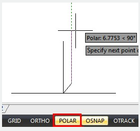
Polar tracking is used to display temporary alignment paths defined by the polar angles you specify, while you are creating or modifying objects. You can set the angle base (ANGBASE)direction in the Drawing Units dialog box.
Alignment paths and tooltips will be displayed when you move the cursor near the polar angles. To draw your object, you can use the alignment path and tooltip. To find, where a polar alignment path intersects another object, polar tracking with Intersection and Apparent Intersection object snaps can be used.
Specify Polar Angles
The polar angle (POLARANG)increments can be set to 90, 60, 45, 30, 22.5, 18, 15, 10 and 5 degrees or other angles which you specify in the Polar Tracking tab of Drafting Settings dialog box.
The orientation of 0 depends on the angle you set in the Drawing Units dialog box (UNITS). The direction of snap (clockwise or counterclockwise) depends on the units direction you specify when setting units of measurement.
Related tutorial video:
- Status bar related setting 00:23
- Line command 00:33
- Polar 00:39
- Edit objects + grips 00:56
- Grips System variable 00:56
- Use grips to edit objects 00:56
- Properties command 01:16
- Display and change the properties of objects 01:16
- Linetype command 01:26
- -Linetype command 01:26
- Control Line Scale 01:26
- Color command 01:33
- Change the color of an object 01:33
- Set the current color 01:33
- Polyline command 02:00
- Fillet command 02:40
- Draw Rectangles and Polygons 03:01
- Revcloud command 03:10
- Donut command 03:14
- Draw Donuts 03:14
- Edit objects + grips 03:23
- Grips System variable 03:23
- Use grips to edit objects 03:23
- ARC command 03:54
- How to draw an arc with specific arc length 03:54
- Circle command 04:42
- Concentric circle command 04:54
- Properties command 05:54
- Mirror command 05:16
- Status bar related setting 00:26
- Line command 00:38
- Draw Lines 00:38
- Menus and Shortcut Menus 00:43
- Object snap 01:05
- Osnap command 01:12
- Draw circles 01:28
- Circle command 01:28
- Polar 03:40
Above video sources from TUTORIAL - GETTING STARTED WITH GSTARCAD, enrol now for free.