OSNAP command
The OSNAP command is used to set object snap modes.
Command Access:
Menu: Tools > Drafting Settings
Status bar: Object Snap
Command : OSNAP
Shortcut : F3
Shortcut : Press SHIFT key and right-click; select "Osnap Settings…"
Command Description:
Users could specify one or more object snap modes by inputting the first three characters of mode name. For more than one names, users could separate them by a comma.
Function Description:
The drafting settings dialog box is used to specify the settings of Snap and Grid,Polar Tracking ,Object Snap.
Dialog Box Description:
There are three option cards in the dialog box: Snap and Grid, Polar Tracking, and Object Snap.
Relative Glossary:
Snap and Grid Tab : Specify Snap and Grid settings.
Snap on : Turn Snap mode on or off.
Snap spacing : Set snap cursor movement to specified spacing.
Snap X Spacing : Specify the snap spacing in the X direction. The value must be a positive real number. (SNAPUNIT system variable)
Snap Y Spacing :Specify the snap spacing in the Y direction. The value must be a positive real number. (SNAPUNIT system variable)
Equal X and Y spacing : Make the X and Y spacing to be the same. The snap spacing intervals could be different from the grid spacing intervals.
Grid On : Turn the grid on or off. Users could also turn grid mode on or off by clicking Grid on the status bar, by pressing F7, or by using the GRIDMODE system variable.
Grid style : Set the grid style in 2D. Users could set grid style by using the GRIDSTYLE system variable.
Display dotted grid in:
2D model space : Set the grid style to be dotted grid for 2D model space. (GRIDSTYLE system variable)
Block editor : Set the grid style to dotted grid for the block editor. (GRIDSTYLE system variable)
Sheet/layout : Set the grid style to dotted grid for the sheet and layout. (GRIDSTYLE system variable)
Grid spacing : Set the grid spacing in X axis and Y axis.
Grid X Spacing : Specify the grid spacing in the X direction. If this value is 0, the grid assumes the value set for Snap X Spacing. (GRIDUNIT system variable)
Grid Y Spacing : Specify the grid spacing in the Y direction. If this value is 0, the grid assumes the value set for Snap Y Spacing. (GRIDUNIT system variable)
Major line every : Specify the frequency of major grid lines compared to minor grid lines. Grid lines rather than grid dots are displayed whenGRIDSTYLE system variable?is set to 0. (GRIDSTYLE system variable)
Snap Style : Set snap type and style.
Grid Snap:
Set the snap type to Grid. The cursor snaps along vertical or horizontal grid points when you specify points. (SNAPTYPE system variable)
Rectangle Snap : Set the snap style to standard Rectangular snap mode. The cursor snaps to a rectangular snap grid when the snap type is set to Grid snap and Snap mode is on.
Isometric Snap : Set the snap style to Isometric snap mode. The cursor snaps to an isometric snap grid when the snap type is set to Grid snap and Snap mode is on.
Grid behavior : Control the appearance of the grid lines when GRIDSTYLE system variable has set to 0.
Adaptive grid : Limit the density of the grid when zooming out. (SNAPTYPE system variable)
Allow subdivision below grid spacing
Generate additional, more closely spaced grid lines when zooming in. The frequency of these grid lines is determined by the frequency of the major grid lines. (GRIDDISPLAYandGRIDMAJOR?system variables)
Display grid beyond Limits : Display the grid beyond the area specified by the LIMIT?command. (GRIDDISPLAY?system variable)
Follow Dynamic UCS : Change the grid plane to follow the XY plane of the dynamic UCS. (GRIDDISPLAYsystem variable)
Polar Tracking Tab : Set the relative options about polar tracking.
Polar Tracking on : Turn polar tracking on and off. Users could also turn polar tracking on or off by pressing F10 or setting the AUTOSNAP system variable.
Polar Angle Settings : Set the alignment angles for polar tracking. (POLARANG system variable)
Increment Angle:
Set the polar increment angle to be used to display polar tracking alignment paths. Users could enter any angle, or select a common angle of 90, 45, 30, 22.5, 18, 15, 10, or 5 degrees from the list. (POLARANG system variable)
Additional Angles : Make any additional angles in the list available for polar tracking.
New : Add up to 10 additional polar tracking alignment angles.
Delete : Delete selected additional angles.
Object Snap Tracking Settings : Set options for object snap tracking.
Tracking orthogonally only:
Display only orthogonal (horizontal/vertical) object snap tracking paths for acquired object snap points when object snap tracking is on. (POLARMODE system variable) Track using all polar angle settings:
Apply polar tracking settings to object snap tracking.
The cursor tracks along polar alignment angles from acquired object snap points when users use object snap tracking. (POLARMODE system variable)
Polar Angle Measurement : Set the basis by which polar tracking alignment angles are measured.
Absolute : Base polar tracking angles on the current user coordinate system (UCS).
Relative to last segment : Base polar tracking angles on the last segment drawn.
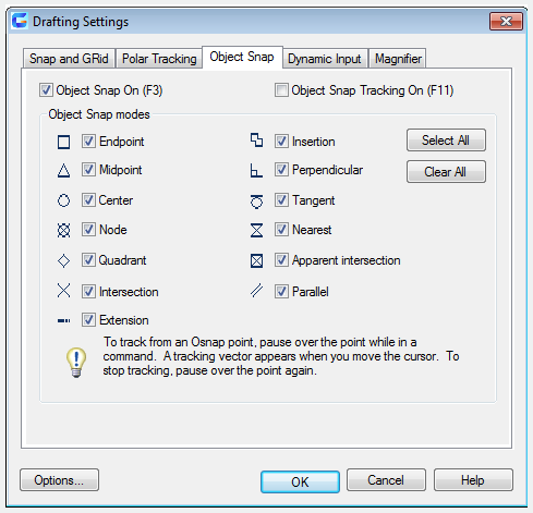
Object Snap Tab:
Control running objects snap settings. Running object snap settings is called Osnap. You can specify a snap point at an exact location on an object with Osnap. When you select more than one option, the selected snap modes are applied to return a point closest to the center of the aperture box. Press TAB to cycle through the options.
Object Snap On : Turn running objects snaps on or off.
Object Snap Tracking On : Turn object snap tracking on or off.
Object Snap Modes : List object snaps that users could turn on as running object snaps.
Endpoint : Snap to the closest endpoint of an arc, elliptical arc, line, multiline, polyline segment, spline, region, or ray, or to the closest corner of a trace, solid, or 3D face.
Midpoint : Snap to the midpoint of an arc, ellipse, elliptical arc, line, multiline, polyline segment, region, solid, spline, or xline.
Center : Snap to the center of an arc, circle, ellipse, or elliptical arc.
Node : Snap to a point object, dimension definition point, or dimension text origin.
Quadrant : Snap to a quadrant point of an arc, circle, ellipse, or elliptical arc.
Intersection : Snap to the intersection of an arc, circle, ellipse, elliptical arc, line, multiline, polyline, ray, region, spline, or xline.
Extension : Cause a temporary extension line or arc to be displayed when you pass the cursor over the endpoint of objects, so you can specify points on the extension.
Insertion : Snap to the insertion point of an attribute, a block, a shape, or text.
Perpendicular : Snap to a point perpendicular to an arc, circle, ellipse, elliptical arc, line, multiline, polyline, ray, region, solid, spline, or xline.
Tangent : Snap to the tangent of an arc, circle, ellipse, elliptical arc, or spline.
Nearest : Snap to the nearest point on an arc, circle, ellipse, elliptical arc, line, multiline, point, polyline, ray, spline, or xline.
Apparent Intersection : Snap to the visual intersection of two objects that are not in the same plane but may appear to intersect in the current view.
Parallel : Constrain a line segment, polyline segment, ray, or xline to be parallel to another linear object. After you specify the first point of a linear object, specify the parallel object snap, then the path of the object is parallel to the previous linear object, an alignment path is displayed, which you can use to create the parallel object.
Select All : Turn on all object snap modes.
Clear All : Turn off all object snap modes.
Related tutorial video:
- Status bar related setting 00:26
- Line command 00:38
- Draw Lines 00:38
- Menus and Shortcut Menus 00:43
- Object snap 01:05
- Osnap command 01:12
- Draw circles 01:28
- Circle command 01:28
- Polar 03:40
Above video sources from TUTORIAL - GETTING STARTED WITH GSTARCAD, enrol now for free.