In some industrial application design, sometimes we need to break pipes or cable lines in our schematic drawing to indicate their spatial relationship. Sometimes we also need to break lines at crossing point to make it convenient for the later edit. Break Object tool came from this kind of needs.
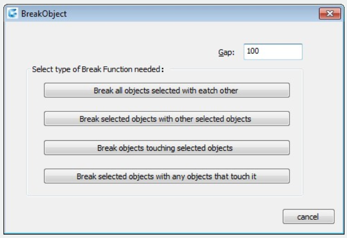
Exploring Break Object Dialog Box

This tool provides four breaking modes with gap distance to visualize the differences between breaking options.
Gap: Indicates the gap value between broken objects.
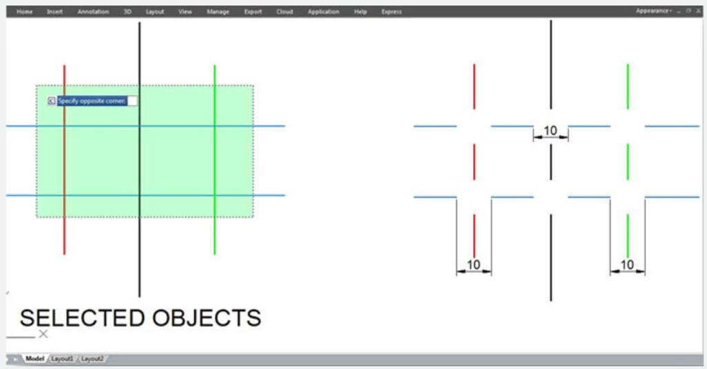
Break all objects selected with each other: This option breaks all intersected objects each other. You can select objects by window selection or picking each object.
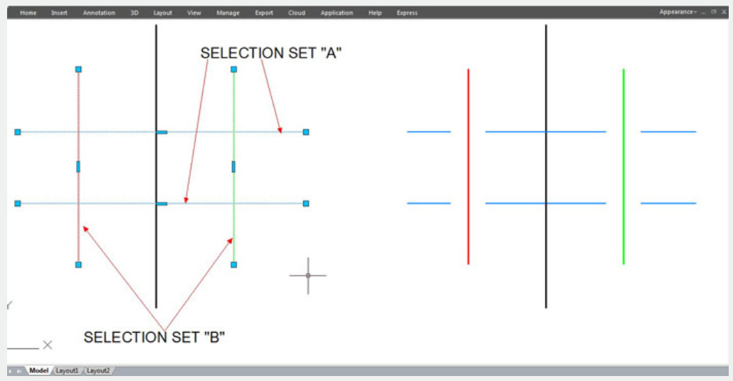
Break selected objects with other selected objects: This option breaks all intersected objects by two selection sets (A and B). The objects selected under the first set (A) will be broken meanwhile the objects selected under the second set (B) will be not broken.
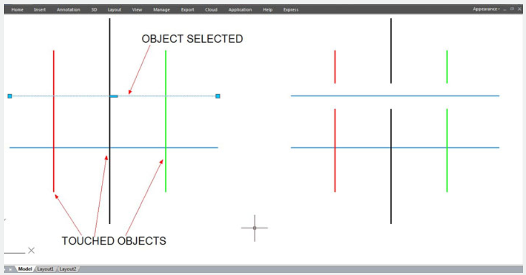
Break objects touching selected objects: This option breaks all intersected objects that touch at first instance selected object.
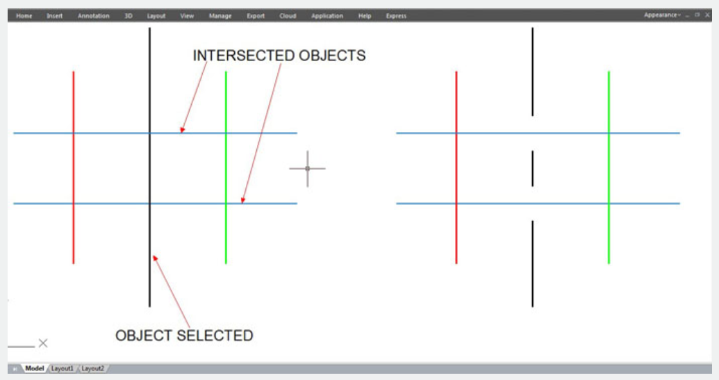
Break selected objects with any objects that touch it: This option breaks the first instance selected object with all intersected objects to it.
Break Object Options Illustration
Break all objects selected with each other: With gap value of 10 for each break point.
Break selected objects with other selected objects: With gap value of 10 for each break point.
Break objects touching selected objects: With gap value of 10 for each break point.
Break selected objects with any objects that touch it: With gap value of 10 for each break point
Above video sources from TUTORIAL - GETTING STARTED WITH GSTARCAD, enrol now for free.
Article ID: 2673
Created: November 18, 2021
Last Updated: April 14, 2022
Author: GstarCAD MY /KW
Online URL: https://kb.gstarcad.com.my/article/break-objects-2673.html