UNITS command
The UNITS command is used to control the display of format and precision of coordinate and angle.
Command Access:
Menu : Application menu > Drawing Utilities > Units..
Menu : Format > Units
Command : UNITS
Function Description:
Uses could set display format, precision and other agreement for coordinates, distance and angle, and then save them in the template; they could also modify those settings in current drawing.
Inputting "-units" under the command prompt, it will display options.
Function Description:
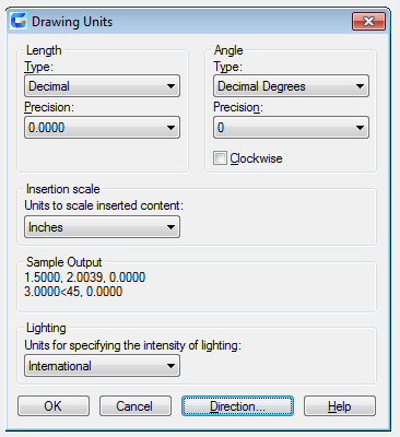
Length:
Specify the unit and unit precision for current measure.
Type:
Set the current format for units of measure. The values include Architectural, Decimal, Engineering, Fractional, and Scientific. The Engineering and Architectural formats produce feet and inches displays and assume that each drawing unit represents one inch. The other formats can represent any real-world unit.
Precision:
Set the number of decimal places or fractional size displayed for linear measurement.
Angle:
Specify the unit and unit precision for current angle.
Type:
Set current angle format.
Precision:
Set the precision for the current angle display.
The following conventions are used for the various angle measures: decimal degrees appear as decimal numbers, grads appear with a lowercase g suffix, and radians appear with a lowercase r suffix. The degrees/minutes/seconds format uses d for degrees, ' for minutes, and " for seconds; for example:
123d45'56.7"
Surveyor's unit show angle as bearings, using N or S for north or south, degrees/minutes/seconds for how far east or west the angle is from direct north or south, and E or W for east or west; for example:
N 45d0'0" E
The angle is always less than 90 degrees and is displayed in the degrees/minutes/seconds format. If the angle is precisely north, south, east, or west, only the single letter representing the compass point is displayed.
Clockwise:
Calculate positive angles in the clockwise direction. The default direction for positive angle is counterclockwise.
When prompting to enter the angle, users could click the direction or input the angle value without regards to "Clockwise" option.
Insertion scale:
Control the unit of measurement for blocks and drawings that inserted to the current drawing. If the unit when they created is different from the specified one, the block or drawing will be scaled when inserting it. The insertion scale is the ratio of the unit used in the source block or drawing and the unit used in the target drawing. Select Unitless to insert the block without scaling it to match the specified units.
Note : when inserting a source block or target drawing, specifying the insertion scale to be unitless, users could set it in the "Source content units" and "Target drawing units" options of User Preferences tab in Options dialog box.
Sample Output :
Display a sample for current settings of unit and angle.
Lighting :
Control the unit of measurement for the intensity of photometric lights in the current drawing.
Note: in order to control light source by creating and using the photometric light, the unit type should not be generic. If the insertion scale has set to be unitless, it will display warning information and announce the user render outputting incorrect.
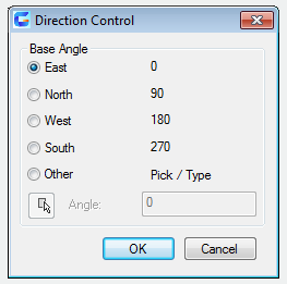
Direction :
Display the Direction Control dialog box.