GstarCAD 2022 Innovative Features
GstarCAD 2022 Innovative Features
Contents
- #GstarCAD Innovation Features
- #Symmetric Draw
- #Autolayer
- #Region Scale
- #Attribute Increment
- #Graphic Compare
- #Update Dimension
- #Rapid Dist
- #Area Table
- #AutoXLS Table Tools
- #Create Table: Menu: Express tools>AutoXlsTable>Create Table Command Entry:_CAOT_AUTOXLSTABLE_CREATE
- #Edit Table: Menu: Express tools>AutoXlsTable>Edit Table Command Entry: _CAOT_AUTOXLSTABLE_EDIT
- #Update Table: Update table whose original Excel spreadsheet was modified.
- #Update All the Tables:
- #Menu: Express>AutoXlsTable>Update All the Tables Command Command Entry: CAOT_AUTOXLSTABLE_UPDATEALLTBL
- #File Link Management: You can use this function to edit, manage the link relation between a table object and an external EXCEL file.
- #Path Settings: This function is used to set the path of an Excel file.
- #Selection Management: You can use this function to calculate objects length and area, when the length and area change, the calculating data will update automatically.
- #Model to Layout Viewport (Layout Viewport)
- #QRcode (pioneer)
- #Magnifier
- #Barcode (pioneer)
- #Outline Objects
- #Free Scale
- #Line Enhancement
- #Polyline Enhancement
- #Rectangle Enhancement
- #Circle Enhancement
- #Copy Enhancement
- #Rotate Enhancement

GstarCAD 2016Activation Guide
GstarCAD Innovation Features
GstarCAD not only provides the features that frequently-used, but also customized a large number of unique and practical features according to user need to speed up your drawing design. The following shows some typical Innovative Features of GstaCAD.
Symmetric Draw
No matter it is AEC or MFG industry, there are many symmetric drawing shapes. The usual way to make a symmetric shape is to draw the first half of the shape and then get another symmetric half by copy or mirror.

In GstarCAD, it is possible to directly draw symmetrical shapes with Symmetric Draw tool. When drawing the first half you get another half automatically. The default symmetry axis is X-axis, but user can specify Y-axis or any line in the drawing as symmetry axis reference.

Users can easily switch on/off this tool by clicking the Symmetric Draw button on the status bar. By the way, Symmetric Draw tool supports all the drawing commands of GstarCAD.


Exploring Symmetric Draw Properties
Right-Click the Symmetric Draw button at status bar and select Settings option. The Drafting Settings dialog box will pop up. Now let’s explore the properties under Symmetric Drawing tab.
Enable Symmetric Draw: Enables the symmetric draw tool if is checked.
Pick Symmetric Axis: You can pick X, Y, or a custom axis to start working with.
Supported Objects: Symmetric draw tool supports line, circle, rectangle, polygon, ray, polyline, ellipse, arc, xline and spline objects to be drawn as symmetrical shape.
Select All/ Erase All: You can select or unselect all supported objects at once.


Symmetric Axis Effect
X Axis option: The objects drawn will take the X coordinate system as invisible axis line. The effect of X Axis is mirroring the drawn objects up or down according to X coordinate system origin location.

Y Axis option: The objects drawn will take the Y coordinate system as invisible axis line. The effect of Y Axis is mirroring the drawn objects right or left side according to Y coordinate system origin location.

Custom/Pick Axis option: The objects drawn will take the vector orientation of a selected object as visible axis line. The effect of Custom/Pick Axis is mirroring the drawn objects according to a selected object vector orientation whether inclined, vertical or horizontal.
Pick Symmetric Axis: At status bar, besides Symmetric Draw button is located another button called Pick Symmetric Axis. The functionality of this button is as same as Custom and Pick Axis options.

Autolayer
Predefine the association between object type and the layer that should be drawn in a drawing. System automatically switches the current layer while drawing the graph, and draws the graphic to the set layer. If the specified layer does not exist, the system will automatically create this layer based on the settings.


About Automatically layer dialog box:
Autolayer list:
Display the command name and the corresponding automatic layer settings.
Create a layer setting:
Create a new layer setting including the command name and the corresponding layer settings.
Delete layer setting:
Delete one or more selected automatic layer settings.
Enable Autolayer:
After checking this check box, the software can automatically assign the layer based on the settings when drawing, if not checked, it doesn’t work.
Save Settings:
Save your current settings to a text file.
Load Settings:
Read the settings file saved by the user and read the settings into the dialog box.
Clear Settings:
Clear all current auto layer settings.
Remark: the current settings only work for the currently edited drawing.
Region Scale

You can select a region of a drawing to be cut and copied to a new location.
Menu: Express tools>Modify>Region Scale Command Entry: _REGSCALE
Command line prompts as follow:
Specify left up corner point for full-page proof: Select a region from left up to right down corner

Specify the position to copy: Specify any place you want to copy to the selected region

Select the object to Trim or shift-select to Extend or [Edge/Fence/Crossing/Project]: Select objects to trim or press Enter to finish the operation.

Input zoom scaling, the block and text will zoom together <Enter- No Zoom>: Press Enter to finish the operation.
Attribute Increment
ATTINC command helps to specify attribute of blocks with incremental value, and to modify attribute value of blocks according to the sort method.
Menu: Express>Blocks>Attribute Increment Command Entry: ATTINC
This command can increase block attribute value that contains a number or letter. When ATTINC command is on, as long as the drawing is not closed, when copying, inserting and deleting a block attribute in the drawing, the property number or letter can be updated automatically.


About Attribute Increment dialog box
Auto Increa:
All referenced properties of the selected block are automatically incremented, which is copied, inserted, deleted in the graph, and the attribute number is automatically updated. When "ATTINC" is on, as long as the drawing is not closed, when copying, inserting and deleting the block in the drawing, the property number can be updated automatically.
Increase the select:
Only the selected block is processed, and the selected block property is incremented by the order of creation.
Select a block:
Click “Select the block” button, and you can pick up a block from the graphics and acquire the name of the block. If there is no attribute in the block you picked up, then prompt: The selected block has no attributes. And you need to pick up again.
Block:
Select a block in block list. If there is no attribute in the block you picked up, then prompt: The selected block has no attributes. And you need to select again.
Select the attribute to increase:
Select the tags to increase. If the block only has one attribute, then the only attribute will be selected automatically. But if the block has more than one attribute, then all the attributes will be displayed and you can select one or more attributes to increase.
Parameter:
Increment:
The attribute value of the selected block is increased by the increment value.
Add ration:
Add the same increment value to the increment number or letter of the attribute value in attribute block.
Increment Mode:
Here are 3 increment modes: Increase every number, Increase the last number and Increase the first number.
Default option is Increase the last number. If there are numbers in the end, these numbers increase as a whole. If you select Increase the first number, and here are numbers in the first, they also increase as a whole. If you select Increase every number, each number in the attribute value is incremented.
Increment Number:
The default number is “1”, and you can modify it if needed.
Sort:
Set the sort of increment as the followings: Draw Order, Select Order, Left to Right, Up to Down and The Path of Curve. The default sort is Draw Order, you can select other sorts.
If you select The Path of Curve, system will prompt you to select a curve. the curve can be a curve or a polyline which intersects with the selected block, and sort according to the order of the point which is closest to the insertion point of each attribute block on the curve. If all the points are as the same point, then according to the distance between each insertion point of attribute block and the curve to sort.
Negative Sequence:
Reverse the order above.
Graphic Compare
As we know the drawing compare function in GstarCAD can be used to compare similar drawings containing nearly number of drawn objects to each other, especially to compare different versions of revision drawings.


Menu: Express tools>Drawing Tools>Graphic Compare Command Entry: OCMP
Drawing compare can make comparisons between two similar drawings (old DWG and New DWG) and generate them as separate files. After pressing COMPARE button within CompareDwg dialog box, the program will generate and open _old and _new.dwg files, where you can see the differences between drawings.
Drawing Compare can find out differences (drawn objects) and show the result with different colors, e.g. if a line is modified, removed or newly drawn, it will be displayed in different colors.


But there is something else that drawing compare could not accomplish so accurately. Drawing compare can’t insert and show the compared objects on the current drawing working space that you are working at real time. Besides, drawing compare can’t show the details of how the objects were located before they were modified.

So the details are very important when comparing objects. Now the new and innovative Graphic Compare tool can do more! It does not only compare two drawingswith similar objects geometry and find out the differences but also display the details of any change at the current workspace of your drawing in real time, e.g. if a line is modified, only the changed part of the line is displayed in different color. The unchanged part remains unchanged.
Graphic compare dialog box
You can invoke the Graphic Compare dialog box by tipping OCMP command at command line or by dynamic input.
Specify Drawing: Offerstwo options of drawing comparison between select objects on your current drawing or specify files.
Select Objects: Offers two options of objects selection including their base points to be compared.
Select base objects and base point: This option allows select all objects, including a basis point as a first selection set to be compared.

Select compare objects and base point: This option allows select all objects, including a basis point as a second selection set to be compared with the first selection set.
Specify File: Checkingthis option allows browse two drawing file to be compared known as base and compare file.
Output Drawing: Offers two options of drawing compared output.
Insert current document: This option allows insert the compared set of selected objects on the current workspace.
Export to a file: This option allows output the compared set of selected objects to a drawing file.
Output settings: You can setup properties like layer, color and linetype for all selected objects to be compared to enhance visual differences between them.
Inserting Compared Objects Set into Current Drawing

To insert compared objects set into current drawing, first select the button Select base objects and base point. Then select allobjects as first selection set called base objects and specify a base point for the base objects.Then select the button Select compare objects and base point and repeat all previous process mentioned above.


Under Output Drawing, check the option Insert current document. If you want setup visual properties for the compared objects, click Output settings button. After that you can place the compared objects set in a convenient point according your need.

Update Dimension
Updates any other dimension(s) to the current dimension style you want to apply.
Menu: Express>Dimension>Update Dimension Command Entry: DIMUPDATE

Command line prompts as follow: -Select a dimension for standard: Select a dimension as a base. -Select a dimension, ensure update the dimension style: Select dimension(s) to be update.
Rapid Dist
Menu: Express>Dimension>Rapid Dist Command Entry: RAPIDDIST

Rapid Dist measures distance and angle between 2D objects along X, Y axis rapidly by moving your mouse.
Distances that only can be measured along X, Y axis based on the position of your mouse, are displayed dynamically as you move your mouse over and between objects. Angles between the objects touched by distance lines are displayed dynamically at the same time.The command only can be used under WCS, and only measure the 2D objects. And the angles of the blocks can’t be measured.

Type “Settings”, you can set unit conversion and scale in
setting window.
Type “Record”, You can save the current result in command line window, which is convenient to check or copy data to other documents.

Area Table
AREATABLE command automatically dimension and count the area of anenclosed object and export the result to a table in the current drawing area.
Menu: Express>Dimension>AreaTable
Command Entry: AREATABLE
The enclosed area or object can be marked with a number or area symbol, and the area table data can be generated at the same time. The area data can be exported to a text or table file. The values in the table can be changed automatically when the number or area size is changed.

AutoXLS Table Tools
Imports, modify and update a CAD table made in Excel spreadsheet to GstarCAD.
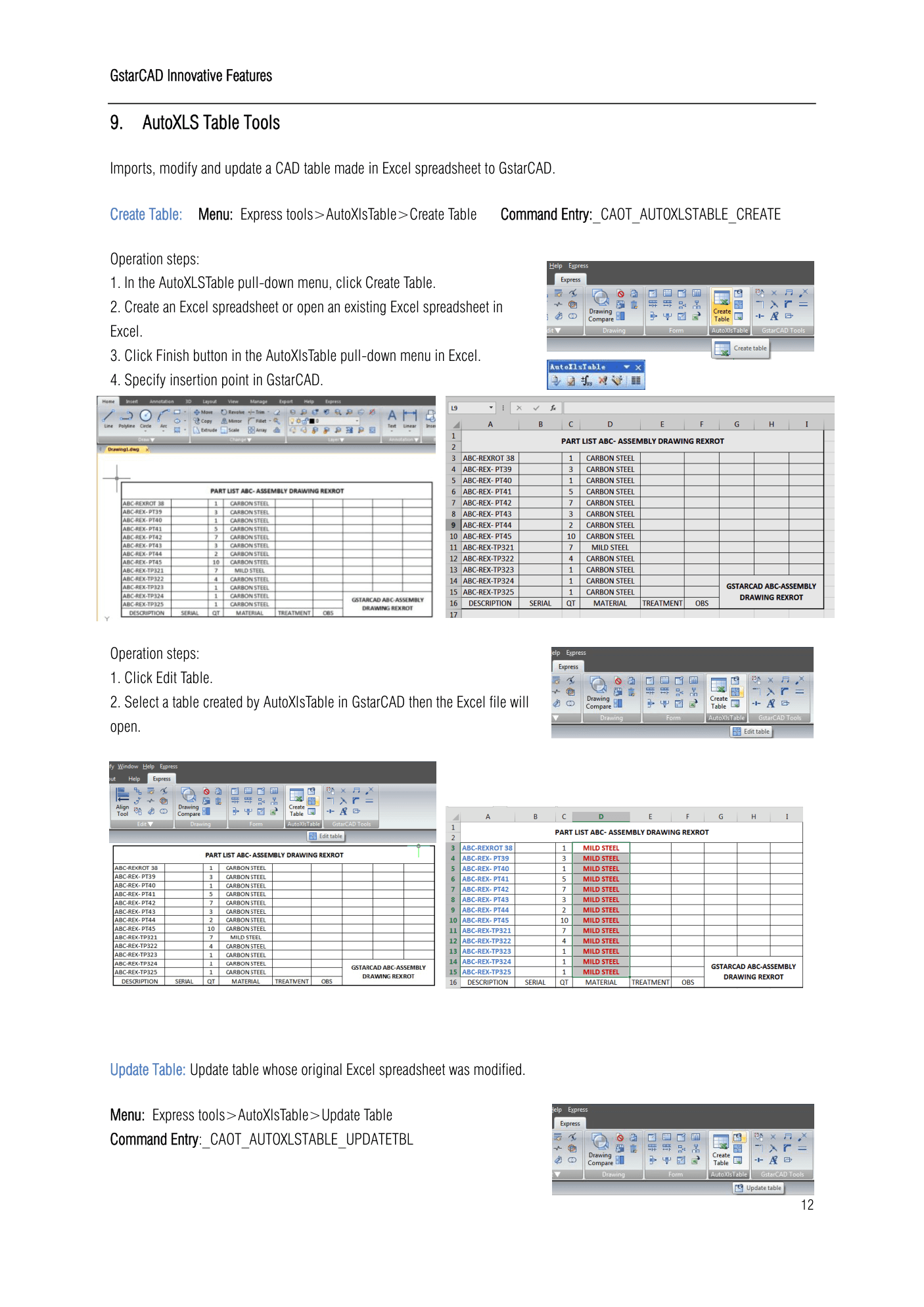
Create Table: Menu: Express tools>AutoXlsTable>Create Table Command Entry:_CAOT_AUTOXLSTABLE_CREATE


Operation steps: 1. In the AutoXLSTable pull-down menu, click Create Table. 2. Create an Excel spreadsheet or open an existing Excel spreadsheet in Excel. 3. Click Finish button in the AutoXlsTable pull-down menu in Excel. 4. Specify insertion point in GstarCAD.


Edit Table: Menu: Express tools>AutoXlsTable>Edit Table Command Entry: _CAOT_AUTOXLSTABLE_EDIT


Operation steps: 1. Click Edit Table. 2. Select a table created by AutoXlsTable in GstarCAD then the Excel file will open.
Update Table: Update table whose original Excel spreadsheet was modified.

Menu: Express tools>AutoXlsTable>Update Table Command Entry:_CAOT_AUTOXLSTABLE_UPDATETBL


Operation steps: 1. Click Update table. 2. Select the table to update then the table will update automatically according to the relevant Excel.
Update All the Tables:
Menu: Express>AutoXlsTable>Update All the Tables Command Command Entry: CAOT_AUTOXLSTABLE_UPDATEALLTBL
After executing this command, the system will update all the table objects created by “Create Table” command.
File Link Management: You can use this function to edit, manage the link relation between a table object and an external EXCEL file.
Menu: Express>AutoXlsTable>File Link Management Command Entry: CAOT_AUTOXLSTABLE_MANAGELINK

Operation steps: 1. Start the command. 2. Select table object in the drawing and a dialog box will pop up. 3. Click the “Browse” button to open the file selection dialog box. 4. Select an XLS file which needs to be connected with a table object and click “OK”, then return to the Link Manager dialog box. 5. You can use the “Attach”, “Delete” and “Update” button to complete link related editing and management.
Path Settings: This function is used to set the path of an Excel file.

Menu: Express>AutoXlsTable>Path Settings Command Entry: CAOT_AUTOXLSTABLE_USINGPATH
Operation steps: 1. Start the command and a dialog box will pop up as below. 2. In the dialog box, you can set the path pattern of the Excel file.
Selection Management: You can use this function to calculate objects length and area, when the length and area change, the calculating data will update automatically.
Menu: Express>AutoXlsTable>Selection Management Command Entry: CAOT_AUTOXLSTABLE_SELECTION
Purpose: use the “Selection Management” function to calculate the area of a circle and a rectangle, when length and area change, the calculating data will update automatically.

- Draw a circle and a rectangle as below, use the “Create Table” function to create a table as below.


-
Start the “Selection Management” command and a dialog box will pop up. 3. Input “CIRCLE” and click the “New Group” button.
-
Select the circle. 5. Press enter, the “Selection Management” dialog box will add a new item “CIRCLE”, as shown below.
-
You can add a “RECTANGLE” item using the same operation as above.
-
Click “Close” to exit “Selection Management”. 8. Use the “Edit Table” command to edit the table. 9. Click the cell on the right side of “CIRCLE” and click the “Insert Function” icon, as shown below:
-
In the dialog box, you can specify the entity as “CIRCLE”, Layer as “All” and click “OK”.


-
Use the same operation to insert the rectangle area calculating function. Then Click the pull-down menu “Finish” option of AutoXlsTabl as shown.
-
Back to CAD and the table will calculate the area of the circle and rectangle. 13. Scale the rectangle and the table data will change automatically.
Model to Layout Viewport (Layout Viewport)
Create a viewport on layout space by selecting objects in the model space. And then calculate the viewport size according to the set ratio and locate the viewport in the layout space. You can quickly create and set a viewport of the graphics.
Menu: View>Layout Viewport Command Entry: _M2LVPORT
Steps to use Viewport from Model
-
In 2D Drafting space. Click “View”>“Layout Viewport” in turn.
-
Specify the first corner point and the diagonal point.
Extents: Obtain the value of the system variables of EXTMIN and EXTMAX in the model space. When EXTMIN and EXTMAX are the same or wrong, the "Extents" option is not displayed. Display: Plot the scope displayed in the Model space currently.
Limits: Obtain the value of the system variables of LIMMIN and LIMMAX in the model space.
When an error scope is obtained, the viewport is not created and shows that "The scope for creating the viewport failed."
- Please select the layout to create
After you select the scope, the system will prompts you to select the layout to create.
-If the command is executed in the Layout space, the viewport is created directly in the layout space of the command.
-If the command is executed in the Model space, the dialog box pops up for you to select the layout.
- Specify the insertion point to viewport
-After setting the layout, automatically switch to the selected layout and specify the insertion point of the viewport.
-You can enter coordinates or click a point to set the location of the viewport in a graphical window.
-After setting the location, the computed viewport is generated at the specified location, and the display locked of the viewport is on.
QRcode (pioneer)
A QR code (quick response code) is a type of bar code that is used to provide easy access to information through a mobile device like smart phone or tablet. Comparing with barcode, QR Code can storage more information and is widely applied in many fields, for example; product anti-fake, advertising push, web links, data download, commodity transaction, Positioning/navigation, electronic documents, business card exchange, etc. Take advantage of QR Code to make text and block attributes from your drawing scannable using any mobile phone or tablet with a camera. All you need is one of many available QR code reader applications for your device.
Menu: Home>Block>QRcode Command Entry: QRCODE

Parameters of QR Code Creator as below: Input:In input text area, you can input the text directly or you can pick text data from the drawing, also you can select the preset data which can display automatically in the input text box. Already entered:0/500:Displays the entered text number and the maximum Input text number. Clear:Cleans all data displayed at input text area. Pick Object: You can select three options to picking objects from your drawing. Text:Picks text from drawing file, the text will display in input text box automatically after you picked up. Block:Picks the attribute block from the drawing file, add the tag and value to the input text box. It is always used to pick the information of the tab. 2D Code: Picks the QR Code from the drawing file to get the information of QR Code Preset Data: You can preset data, when the data is needed just check the corresponding option. The information will automatically added to the input text area. Drawing Name: When check Drawing Name option, the drawing name will display in the input text area. Date and Time: When check Date and Time option, the current date and time will display in the input text area.

Parameters of Costumed Field as below:
Name>Add/Edit: You can customize field that common used, when the field is needed, click the pull down list to find it out and display it in input text box.
No: Input the field number. Name:Input the field name. Value: Input the field value. Add:Add new custom field. Delete: Delete custom field. Image: Company logo or others marked pictures can be added to QR Code. You can also browse pictures from your computer, JPG\BMP\PNG\TIF\TGA.etc formats are supported. Delete: Delete the picture selected.

QR Code Parameters: You can set QR Code image parameters before being inserted. Version:Creates QR Code according to the data you input. Sets the QR Code version and the version number will adaptively according to the increase of text. Error Level:Error level for QR Code data generated. Size:Set the width of QR Code. H (30%)\Q(25%)\M (15%)\L (7%): the compatibility of correcting about 15% data error. Code:QR Code system. Currently we support Code93. Scale:Set the QR Code printing scale, behind the scale option is the scale list. You can choose the scale needed, meanwhile, the scale list can remind user the QR Code generating is related to the printing scale. Finally, it will generate as a block, the scale you set can be the block scale to ensure the QR Code can be printed correctly in different printing scales.

Copy Barcode: Copies an existing QR Code from your current drawing. Save Image: Saves the QR Code as a picture, you can either use the picture to print or insert to other document or to CAD drawing. Insert: Inserts the generated QR Code to the drawing as a block Cancel: Cancel the dialog box and save the current settings, when you open the dialog box next time, the setting you saved last time will be displayed.
Magnifier
MAGNIFIER (a real alternative to change the habit of viewing details and drafting over the most complex drawing at glance). This tool helps to view a specific area of your drawing as a magnifier with the capability of snap points without performing zoom in/out on big drawings like map or survey and also is practical to use and customize. Save time on exploring small details of your drawing or even drafting in a jungle of intersected objects easy and quickly.

1.- Before execute MAGNIFIER command, let’s explain its settings. At the status bar there is a magnifier icon, just right click mouse and select the option > settings…

2.-In the Drafting Settings dialog box, under Magnifier tab, we will see several options. Let’s explain one by one.

Enable Magnifier by Scroll button: If you check this option you can enable/disable the magnifier command by clicking the scroll wheel of the mouse. Also the shortcut key Ctrl+E is available to activate magnifier.
Magnifier Style
Region: When activating the magnifier, it will magnify the spot you select from your drawing within the magnifier shape. The cursor only can move in the magnifier shape. You can execute zoom, pan, and draw objects, etc to see the bigger and clearer details.
Window: When activating the magnifier, it will not only magnify the part you select, but also magnify the whole drawing according to the magnifier factor you set. With window style, the cursor can move in and out of the magnifier shape. The operations, for example zoom or draw objects will not be restricted in the shape of magnifier.
Magnifier Shape Square: If you choose square option, the magnifier will adopt a square shape. Circle: If you choose circle option, the magnifier will adopt a circle shape.
Magnifier Size: You can adjust the magnifier shape size as you like.
Fade Control: You can adjust the fade effect out of the magnifier shape.
Magnifier Factor: You can adjust the zoom factor within the magnifier shape.
Barcode (pioneer)
Barcode technology has been widely used in a variety of industries. In some design companies, barcode has also been used in drawing management system, mainly used to corresponding paper documents and electronic drawing file, just by scanning the bar code in the paper drawing to identify quickly the corresponding part in electronic drawing file.

Parameters of Bar Code Creator as below:
Width: Set the bar code printing width. Height: Set the bar code printing height. Scale: Set the barcode printing scale, behind the scale option is the scale list, you can choose the scale needed, meanwhile, the scale list can remind user the bar code generating is relate to the printing scale. Finally, barcode will generate as a block, the scale you set can be the block scale to ensure barcode can be printed correctly in different printing scales. Display Data: Control whether displays the data under the bar code. Size: If “Display data” option is checked means option is activated, you can set the data height. Code:Bar code system. Currently we support Code93. Preview: Displays the bar code image and the data input. Data input box:You can directly input bar code data, also can click seed to generate barcode. Seed: Generate barcode data by random algorithm. Click the "seed" button, the barcode data will generate randomly and display directly to the data input box above. Length: Set the length of the bar code data. There are two ways: one is control the data length which manually input and random generated. The other is control the data length that random generated, check the "seed" before activate this setting. Pick: Pick up text or bar code. If you pick the data, it will only obtain the data displayed, but if you pick the barcode, you will get the information of barcode width, height and proportion and data Save Image: Save the barcode to BMP format picture, you can either use the picture to print or insert to other document or to CAD drawing. Insert: Define the barcode generated as a block and take left bottom of the barcode as base point. You can insert the barcode to the drawing file through the insertion point with the scale set before. Cancel: Cancel the dialog box and save the current settings, when you open the dialog box next time, the setting you saved last time will display.
Outline Objects


OUTLINE command is another innovative tool of GstarCAD. This tool allows extract the outline shape of selected closed objects in a window selection method. This outlined shape is in fact a polyline object created on the current layer that you are working with.
For example, use this tool extract the outline shape of a floor plant house to later calculate its total area or to reference draw the roof of it.
Remark: Other innovative features, such as Break Object, Block Break, Graphic Compare, Pline Boolean, Align tool, Arrange Tool, AutoXLSTable, CAD Table to Excel, Text Incremental Copy, Statistics Summation, Text on line, GstarCAD Tools, Drawing Compare, Drawing Lock, Batch Purge, etc. Please refer to the express tool guide.
Free Scale
FREESCALE command allows you to scales an object or a group of objects without restrictions under three methods; Non-Uniform, Rectangle and Free.
Non-uniform scale: The scale of X and Y axis can be input separately.
Rect Scale: You can scale a graphic to match a rectangle frame. The rectangle does not need to be drawn, just specify two diagonal points.
Free Scale: You can move or copy and scale the graphics in a closed quadrilateral frame to another closed quadrilateral frame, which can be used to generate the pattern of tilting or perspective distortion graphics.

Line Enhancement
ANGLE (A) option is added for line command, with this option you can get a fast way to draw a line without assistance of the polar or a xline. You can directly input the angle value refers to X axis as well as you can take other line as reference to input the angle value and even you can input the angle value directly refers to previous line.

Practice example:

To draw the red line in Figure 1-1, the steps as below:
- Execute line command
- Specify first point:
- Specify next point or [Angle/Length/Undo]:a
- Specify angle [Reference] <0>:35(Software will take the X axis as reference)
- Length of line: 500

To draw the red line in Figure 1-2, the steps as below:
- Execute line command
- Specify first point:
- Specify next point or [Angle/Length/Undo]:a
- Specify angle [Reference] <0>:r
- Select a line object: (Please select the reference line)
- Specify an angle: 38 7. Length of line: 500
To draw the red line in Figure 1-3, the steps as below:
- Execute line command (to draw the line 1).
- Specify first point:
- Specify next point or [Angle/Length/Undo]: l
- Specify length: 300
- Specify next point or [Angle/Length/Undo] (to draw the line 2): a
- Specify angle [Reference/reference to Previous/Included angle] <0>: p(Here you can try reference to Previous option which will take the extension of the previous line as reference)
- Specify an angle: 127
- Length of line: 500
- Specify next point or [Angle/Length/Closed/Undo]:a (to draw the line 3)
- Specify angle [Reference/reference to Previous/Included angle] <0>: I (Try Included angle option)
- Specify an angle: 37
- Length of line: 400
Polyline Enhancement
Polyline Enhancement
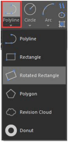
The ANGLE (A) option in polyline command which its behavior is similar as the one in line command is also added in Polyline. There are still three choices for angle option, you can either input angle value which takes X Axis as reference as well as you can input “reference to Previous” angle or “Included angle”. In CAD software, many objects are consisting of Polyline, for example: rectangle, polygon and revision cloud, donut. Now these functions are classified under the Polyline drop down list where you can access them quickly.
Rectangle Enhancement
OBLIQUE(O) is a new added option to draw an rotate rectangle. The behavior of oblique option is similar as the behavior in line command. With oblique option, you can locate the angel of bottom line and the length to get a rotate rectangle, you can draw an oblique rectangle which has specific angle with X axis and horizontal or has random angle refer to any line.

Practice example:
To draw the rotate rectangle in Figure 1-4, the steps as below:
- Execute RECTANG command and input oblique option or click the rotate rectangle icon in ribbon panel.
- Specify first point:
- Specify next point or [Angle]: a(Input Angle option)
- Specify angle [Reference] <0>:20
- Enter rectangle width: 800
- Enter rectangle height: 350

To draw the rotate rectangle when there is a reference line in Figure 1-5, the steps as below:
- Execute RECTANFG command and input oblique option or click the rotate rectangle icon in ribbon panel.
- Specify first point:
- Specify next point or [Angle]a
- Specify angle [Reference] <0>:r
- Select a line object: (Select the reference line)
- Specify an angle: 20
- Enter rectangle width: 800
- Enter rectangle height: 350
Circle Enhancement
CONCENTRIC(C) option is new added in circle command, you can input radius several times to create many concentric circle after specify the circle center, with this new option, you can get concentric circle in a simple way.

Practice example:
To draw the concentric circle in Figure 1-6, the steps as below:
- Execute circle command and input concentric option or click the concentric icon in ribbon panel.
- Specify center point for circle:
- Specify the radius of circle or [Diameter] <400.0000>:100
- Specify the radius of circle or [Diameter/Undo] <100.0000>:200
- Specify the radius of circle or [Diameter/Undo] <200.0000>:300
Copy Enhancement
There are three options: measure(E), divide(I), path(P) options are added in copy command, user can easily finish the drawing without the assistance of other operations such as divided by segment, by distance, array, or layout bypath in previous version.

- measure(E)when users need to copy objects with same distance and same direction, this option will be very useful.

-
Divide(I), you can copy many objects with same distance in a specified distance.
-
Path(P)After select the path option, you can select divide or measure option again to locate the count objects.

Rotate Enhancement

Multiple copy (M) option is added in rotate command, with this option, you can either copy many objects with different rotate angles, or you can draw circles array. When rotate, you can select multiple copy option and input several angle values; the software will rotate and copy the object according to the value you input. You can try copy and rotate 45, 90,135 degree refers to the original object at a time such as the following figure.
Practice example: Rotate and copy objects in Figure1-7, the steps as below:
- Execute the Command: ROTATE
- Select object:
- Specify the base point: (Select the center of the concentric)
- Specify rotation angle or [Copy/Multiple/Reference] <135>: m
- Specify rotation angle or [Between/Fill]: 45
- Specify rotation angle or [Exit/Undo]: 90
- Specify rotation angle or [Exit/Undo]: 135

If the adjacent object angle is fixed, you can select “angle between object(B)or fill angle(F)option, then input the angle and the quantity, this option can replace circle array.
Rotate and copy objects in Figure1-8, the steps as below:
- Execute the command: ROTATE
- Select object: (Select the center of the concentric)
- Specify the base point:
- Specify rotation angle or [Copy/Multiple/Reference] <30>: m
- Specify rotation angle or [Between/Fill]: b
- Specify rotation angle: 60
- Specify total number of items: 4

Rotate and copy objects in Figure1-9, the steps as below:
- Execute the command: ROTATE
- Specify the base point: (Select the center of the concentric)
- Specify rotation angle or [Copy/Multiple/Reference] <60>: m
- Specify rotation angle or [Between/Fill]: f
- Specify angle to fill<360>:
- Specify total number of items: 1
Remark: The above only lists parts of the innovative features.
Learn more about GstarCAD innovative features, please refer to the GstarCAD Express Tool Guide.