GstarCAD 2022 Express Tools
GstarCAD 2022 Express Tools
Contents
- #Block Tools
- #Replace Block with Another Block: In the current drawing, you can use one block to replace another one, moreover, you can purge the unreferenced block when the operation is finished.
- #Copy Nested Objects: Copy objects in an xref or a block.
- #Explode Attribute to Text: Explode blocks, converting value of attributes to text objects.
- #Attribute Increment: ATTINC command helps to specify attribute of blocks with incremental value, and to modify attribute value of blocks according to the sort method.
- #Export Attribute Information: Export block attribute to an external file in tab-delimited ASCII format.Menu: Express>Blocks>Export Attribute Information Command Entry: ATTOUT
- #Import Attribute Information: Import block attribute to an external file in tab-delimited ASCII format.Menu: Express>Blocks>Import Attribute Information Command Entry: ATTIN
- #Statistics Blocks Number: You can statistics the quantity of various blocks through this function.
- #Count Blocks: This function is used to count the number of the blocks by list.
- #Change Block Color: Modify the block color quickly.
- #Change Block Linewidth: This function can modify block linewidth quickly.
- #Change Block Text Angle: This function can change the text rotation angle of the block and it only takes effect on text or mtext, attribute text can’t be changed.
- #Change Block Text High: This function can change the height of the block, it only takes effect on text or mtext, attribute text can’t be changed.
- #Change Block Layer: This function can change the block layer.
- #Convert BLOCK to XREF: Replace all instances of a standard block with an xref. Unbind xrefs that are bound.
- #List Xref/Block Properties: List the type, block name, layer name, color and linetype of a nested object in a block or an xref.
- #Menu: Express>Blocks>List Xref/Block Properties Command Entry: XLIST
- #Trim to Nested Objects: Trims objects with a block as a cutting boundary.
- #Extend to Nested Objects: Extends objects such as line segment, arc, polyline or ray to a block. Objects would be extended to a block as close as possible if they cannot intersect with each other.
- #External Reference Relocate: With this function, our software can recognize the reference in the drawing and give you the reference state, if you want to select another reference path, click the “Relocate” button and the reference will be displayed in the drawing again.
- #Text Tools
- #Justify Text: Change a text object's justification without changing its position. Works with text, mtext, and attribute definition objects.
- #Rotate Text: Aligns text, mtext and block attribute objects to new orientation. Rotates text, mtext, and attribute definition objects so that they end up being as close as possible to horizontal or right-read (similar to the behavior of dimension text). Objects are rotated about their middle point in 180-degree increments. For example, if the text is upside-down, it becomes right-side up after a TORIENT operation. Similarly, left-read text becomes right-read text.
- #Change Text Style: This function can change current text style for specified text and single line text, multiline texts are available.
- #Chinese Characters Split: This function can split single line texts to single text one by one, because the English word is a combination of several letters, this function only make sense for Chinese Characters.
- #Character Break: Menu: Express > Text Tools > Character Break Command Entry: WZDD
- #Change Character: This function can continuously revise multiple text objects, single line and Mtext are applicable.
- #Change One Character: This function can change texts in selected single line texts, you can just input characters to be replaced and characters to replace according to the prompts, Moreover it can be used in several single line texts at the same time.
- #Change Text Height/Width/Angle/Position: This function is used to modify text height, text width, text angle and text position. You can click or select characters by window selection.
- #Delete Annotation: This function is based on this kind of circumstance, you can select one text annotation to be deleted , the software will register all the annotations in one layer, you can just press enter and all the text annotations will be deleted or you can select the texts by window selection and it will not affect the texts of other layers.
- #Adjust Character: When the texts are mixed with Chinese characters, English letters and Arabic numerals, the text height will be different and the visual effect is not good. You can use this function to match the text height, but this function will explode the text's and it will be difficult to re-edit, so we suggest using this function after the user finished editing the drawing.
- #Layout Tools
- #Dimension Tools
- #Change Dimension Text: Change the dimension content into the specified value.
- #Change Dimstyle: Apply the current dimension style to the dimensions in the drawing.
- #Reset Dim Text Value: Restore a measurement value to overridden or modified dimension text. Menu: Express>Dimension>Reset Dim Text Value Command Entry: DIMREASSOC
- #Update Dimension: Updates any other dimension(s) to the current dimension style you want to apply. Menu: Express>Dimension>Update Dimension Command Entry: DIMUPDATE
- #Dimstyle Export: Exports named dimension styles and their settings to an external file.
- #Dimstyle Import: Imports named dimension styles from a DIM file into the current drawing.
- #Detach Leaders from Annotation: Detach leader line from mtext, tolerance, or block reference object.
- #Global Attach Leader to Annotation: Globally attaches leaders line to mtext, tolerance, or block reference objects.
- #Selection Tools
- #Get Selection Set: Create a temporary selection set of objects.
- #Fast Select: Selects the object that touches the specifide object.
- #Filtrate Selection Select, edit, and name filters for object selection.
- #Get Selection by Block Name: You can use this function to multi-select objects with the same name in specified area.
- #Get Selection by Color: Quick select the objects with the same color. Menu: Express>Selection Tools>Get Selection by Color Command Entry: GETCOLSELOperation steps: 1. Start the command. 2. Select one object and system will take the object’s color as target color. 3. Specify region. 4. System will select the objects which have the same color as the target object automatically.
- #Get Selection by Object/Layer: Select entities by entity type and layer. Menu: Express>Selection Tools>Get Selection by Object/Layer Command Entry: GETENTLAYSELOperation steps: 1. Start the command. 2. Select one object and system will take the object layer as target layer. 3. Specify region. 4. System will select the objects which are in the same layer and with same entity type automatically.
- #Get Selection by Object/Color: Select entities by entity type and color. Menu: Express>Selection Tools>Get Selection by Object/Color Command Entry: GETENTCOLSEL Operation steps: 1. Start the command. 2. Select one object and system will take the object’s color as target color. 3. Specify region. 4. System will select the objects which have the same entity type and color as the target object automatically.
- #Get Selection by Layer/Color: Select entities by color and layer. Menu: Express>Selection Tools>Get Selection by Layer/Color Command Entry: GETLAYCOLSELOperation steps: 1. Start the command. 2. Specify an entity which is in the target layer. 3. Specify region. 4. System will select the objects which have the same color and same layer as the target object automatically.
- #Modify Tools
- #Layer Draworder: Rearranges the layer order to adjust the sequence of the objects.
- #Draworder by Color: Arranges the drawing order of selected objects by their color number.
- #Move/Copy/Rotate: Move, copy, rotate, and scales object(s) with a single command.
- #Region Scale: You can select a region of a drawing to be cut and copied to a new location.
- #Trim Enhancement: Trim one side of an object which is intersecting with other objects. The object can be polyline, line, circle, arc, ellipse, image or text.
- #Extended Offset: This enhanced version of the OFFSET command offers several advantages over the standard command, including layer control, undo, and a multiple option.
- #Multiple Pedit: This command is almost the same as the standard command.
- #Delete Duplicate Objects : This function can not only manage overlapped lines, circles, Plines linear objects etc, but can also manage entire coincident blocks, texts, dimensions and regions .Moreover, remove does not simply mean delete, it judges by layer, color, line type and many relevant attributes and can delete or connect coincident parts of 2D and 3D Plines, circles, arcs and overlapping line parts. Using this option can not only delete redundancy objects, but can also avoid editing and printing problems caused by overlapped objects.
- #Multiple Copy: Copy multiple objects with Repeat, Array, Divide and Measure options.
- #Layout By Path: Unlike common array function, LayoutByPath distributes object copies along a path (curve) with a variety of array options. Users can choose ra8ndom, division and measure options and array in different directions along the path.
- #Draw Tools
- #Breakline Symbol: Creates a polyline and inserts the breakline symbol. The options within this command are provided to control the relative size and appearance of the breakline symbol and an extension of the polyline beyond the selected start and end points.
- #Spline to Pline: With this tool the SPline created can be converted to a polyline according to the accuracy (number of segments of the arc) that the user assigns. The more specified the segment number is, the higher is the matching degree between the converted Polyline.
- #Line to Pline: This function can convert one or multiple connected straight line(s), arc(s) to one polyline. You can access from:
- #Tools
- #Command Alias:This function allows users to add, modify, delete command alias and shell commands.
- #System Variable Editor: Allows you to view, save, load and compare system variable settings.
- #Make Linetype: Creates a linetype based on selected objects.
- #Make Shape: Creates a shape definition based on selected objects.
- #Table Tools
- #Draw Table: This function can help you draw a table.
- #Fig 14Split Cells: This function is similar to split cells in Excel.
- #Add Bias: This function can add bias for a cell. Click the start and end point according to the prompts and the system will provide an intersection snap and can easily find the start and end point of the bias, or you can click any area in one cell and the system will find the top left point of the cell automatically, then the system will prompt you to select the end point, you can also click any area in the cell, system will take the bottom right point as the end point automatically, this way, a bias is added in a cell.
- #Drag Multiple Lines: You can change the row and column width by dragging the line of the table and the corresponding parts of the line will also change. For example, drag the line you selected to the right side and all the lines in the right side will move to the right side correspondingly.
- #Drag Line: Different to Multiline drag, Drag line will just move the line you selected and other relevant lines will not move.
- #Drag Segment: This command will not change the lines of the whole table, but just move the side line of a cell.
- #Selection Scale: This function can zoom in and zoom out the whole table base on the point you specified.
- #Add Row: This function can add rows to the table.
- #Add Column: This function can add new columns to the table.
- #Delete Row: This function can delete the row of the table you specified.
- #Delete Column: This function can delete columns you specified.
- #Delete Table: This function can delete the table you selected.
- #Text Orientation Adjust: This function is used to adjust the alignment of the texts.
- #CAD Table to Excel: This command will convert sheets, composed by line/Spline and text/Mtext in CAD, to EXCEL.
- #Coordinate Tools
- #Drawing Tools
- #Drawing Compare: Drawing compare is an exclusive function in GstarCAD which is added according to the user’s requirement. It enhances collaboration by using color-coded displays to show items on a drawing that have been changed, added, or deleted by other members of the design team. Changes to items such as styles, block attribute, object of block can also be tracked. The program will analyze the differences between two drawings automatically. Then the differences will be marked with different colors. Users can also set the marking color by clicking the “option” button.
- #Drawing Lock: Sometimes a designer sends drawings to other people, but doesn’t want others to modify the drawings. The “Drawing Lock” function can turn the drawing into a whole block. You can’t explode it or modify the objects of the original drawing. It is a good way to prevent others from modifying the drawing.
- #Batch Purge (Batch Files Cleaning): This new function allows to batch purge the excess objects such as blocks, layers, line type, dimension style or text style on several DWG files. The Batpurge tool doesn’t need to open files. It executes the command of purge directly, which makes it run with very high efficiency. You can access it from:
- #Move BAK: Changes the destination folder for drawing backup (BAK) files.
- #AutoXlsTable
- #Create Table: Menu: Express tools>AutoXlsTable>Create Table Command Entry:_CAOT_AUTOXLSTABLE_CREATE
- #Edit Table: Menu: Express tools>AutoXlsTable>Edit Table Command Entry: _CAOT_AUTOXLSTABLE_EDIT
- #Update Table: Update table whose original Excel spreadsheet was modified.
- #Update All the Tables:
- #Menu: Express>AutoXlsTable>Update All the Tables Command Entry: CAOT_AUTOXLSTABLE_UPDATEALLTBL
- #File Link Management: You can use this function to edit, manage the link relation between a table object and an external EXCEL file.
- #Path Settings: This function is used to set the path of an Excel file.
- #Selection Management: You can use this function to calculate objects length and area, when the length and area change, the calculating data will update automatically.
- #GstarCAD Tools
- #Drawing Scale: You can set the drawing scale before drawing, when you are using other tools (for example “Line Such as Chord” and “Modify Line width”), our software will adjust the scale automatically.
- #Rotate Cursor: The cursor can rotate anti-clockwise by 0 degree or 45 degree.
- #Side Line: Menu: Express>GstarCAD Tools>Rotate Cursor>Side Line Command Entry: RTCUR1
- #Real Time Rotate:
- #Menu: Express>GstarCAD Tools>Rotate Cursor>Real Time Rotate Command Entry: RTCUR
- #Draw Axonometric Line: Using this function can easily draw an axonometric drawing.
- #Visual Extension: Normally after extension, the extension effect will be displayed, but Visual Extension can display the effect in real time until you confirm the position.
- #Normal Connect: The Normal Connect function is similar to zero distance chamfer, it can delete the lines of actual intersection or apparent intersection parts.
- #Flex Connect: This function can extend or cut down the line to the actual intersection or apparent intersection point.
- #Super Fillet: This function can not only do the fillet operation but can also unify the filleted line layer, color and line type and the unified standard will take the first selected fillet object as reference.
- #Modify Linewidth: Modify the line width you specified, if what you specified is a line and our software will convert the line to Pline automatically and change the line width. This function is similar to the pedit function, we can use it as a shortcut version and it is very convenient for modifying the line width.
- #Cross to Break: In engineering drawings, many places need to break the cross line. If we do this the original way, it will be very complex. Using this function breaking lines can be easily done.
- #Control Break Width: This function is used to set break width for cross objects.
- #Modify Text: In here you can find several tools to modify text properties.
- #Text Height: Menu: Express tools>GstarCAD Tools>Modify Text>Text Height Command Entry: TXT40
- #Width Factor: Menu: Express tools>GstarCAD Tools>Modify Text>Width Factor Command Entry: TXT41
- #Angle: Menu: Express tools>GstarCAD Tools>Modify Text>Angle Command Entry: TXT50
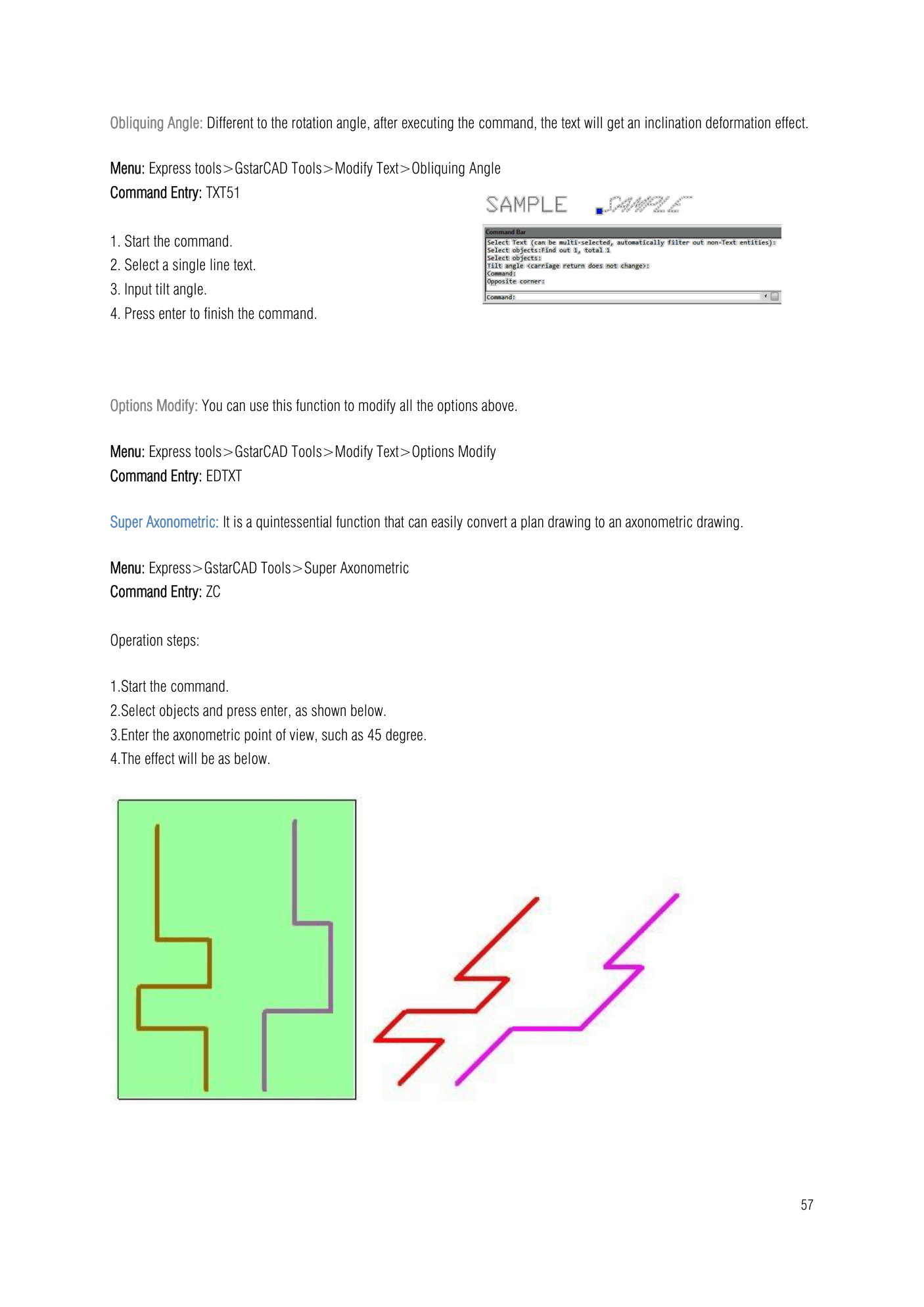
- #Obliquing Angle: Different to the rotation angle, after executing the command, the text will get an inclination deformation effect.
- #Options Modify: You can use this function to modify all the options above.
- #Super Axonometric: It is a quintessential function that can easily convert a plan drawing to an axonometric drawing.
- #Plot Tools
- #Print PLT: Users can send PLT files to printer for printing.
- #Batch Print: Batch print drawings with the same drawing frame attribute.
- #Arrange Frame Automatically: This function can search frames automatically, calculate according to the size of the frame and then arrange several drawings to a big drawing.
锹钾

movebak
GstarCAD 2016Activation Guide
Express Tools
The GstarCAD Express Tools contain a library of productivity tools designed to help you extend the power of your design. They are easy to use, easily integrated into your menus and toolbars, and cover a wide range of functions, including dimensioning, drawing, and selecting and modifying objects. GstarCAD Express Tools are organized on:
Block Tools

Change base: The CHANGEBASE command allows changing the base point position of a block. You can move the base point and keep objects staying in same position, or move objects and keep base point staying in same position
Menu: Express tools>Blocks>Change Base Command Entry: CHANGEBASE
Block Break: Working with block references that represent symbols are essential in some industrial application drawings like electrical schematics, piping, etc.
But a headache comes when try to place these blocks accurately overlapping or even breaking other objects on your drawing.
Now get rid of this headache with BLOCKBREAK command. This innovative tool is able to wipeout or breaks an object that is overlapped by a reference block.
For example, insome cases we may need to insert block symbols into a cable line in electrical schematic. And normally the cable line is required to be broken by the symbols at where the symbols are inserted. Similar request are also exists in other application designs.
Menu: Express tools>Blocks>Block Break Command Entry: BLOCKBREAK
Block break dialog box:

Name: List all available blocks created in the drawing.
Browse: Browse to open specific drawing file.
Pick: You can pick an existing block reference in the current drawing.
Scale: Scales the block reference size according to X, Y and Z coordinates. Uniform Scale option keeps the original size of block reference.
Rotation: You can rotate a block reference by inputting an angle value or keep aligned.
Process Mode: You can use a block reference to break or wipeout objects when overlapping.
Block Break Process Mode Illustration
Break: Breaks background object(s) when a block reference is overlapped.

Wipeout: Wipeout background object(s) when a block reference is overlapped.

Replace Block with Another Block: In the current drawing, you can use one block to replace another one, moreover, you can purge the unreferenced block when the operation is finished.

Replace Block with Another Block: In the current drawing, you can use one block to replace another one, moreover, you can purge the unreferenced block when the operation is finished.

Menu: Expresstools>Blocks>ReplaceBlock Command Entry: BLOCKREPLACE
Select a block to replace: Double bed. Then select: OK Select the block to be replaced: Sofa. Then select: OK Purge unreferenced items when finished? Yes/No


See the result below:
Copy Nested Objects: Copy objects in an xref or a block.
Menu: Express>Blocks>Copy Nested Objects Command Entry: NCOPY
Command line prompts as follows:
Select nested objects to copy: Use an object selection method Base point: Specify a point, or enter M for multiple copies Specify second point or <use first point as displacement>: Specify a point
Explode Attribute to Text: Explode blocks, converting value of attributes to text objects.
Menu: Express>Blocks>Explode Attributes to Text Command Entry: BURST
Command line prompts as follows: Select entities: Use an object selection method
For example: Explode attributes and convert them to text objects.
- Select a block containing two attributes. 2. Block exploded and attribute values converted to text.


Attribute Increment: ATTINC command helps to specify attribute of blocks with incremental value, and to modify attribute value of blocks according to the sort method.
Menu: Express>Blocks>Attribute Increment Command Entry: ATTINC
This command can increase block attribute value that contains a number or letter. When ATTINC command is on, as long as the drawing is not closed, when copying, inserting and deleting a block attribute in the drawing, the property number or letter can be updated automatically.


Export Attribute Information: Export block attribute to an external file in tab-delimited ASCII format.Menu: Express>Blocks>Export Attribute Information Command Entry: ATTOUT

Once performed ATTOUT command, specify file name and save path in "Enter output filename" dialog box, then command line prompts: Select entities: Specify the blocks whose attributes you want to export.
The block names and attributes are exported to the named file. If the file already exists, you are prompted before it is overwritten. You can easily view attributes in a spreadsheet format and edit individual attribute values. Then you can enter the new values into the drawing file, using the ATTIN command.
Import Attribute Information: Import block attribute to an external file in tab-delimited ASCII format.Menu: Express>Blocks>Import Attribute Information Command Entry: ATTIN
Using ATTIN and ATTOUT together, you can quickly make changes to attribute values for selected block references.

Once this command is performed, the "Enter input filename" dialog will pop up for the user to search file, import the block attributes along with the same handle and block name into the drawing, and make changes to the block attributes as well.
Once an attribute value is modified, it will be integrated into the specified block. It should be noticed that the imported file can't be attribute file exported by ATTOUT command, whereas the file format should be identical to that of ATTOUT command exporting.
Reads through imported file and processes each line when performing ATTIN command. If the block with the same handle and name is found in the process of treating lines, the modified attribute value of this block will be applied. If several blocks with the same handle and name are found, then system prompts whether to interactively assign saving data when processing these blocks. If "Yes" is selected, the data of each command line will be listed enabling selection of a block to apply this attribute. Press ENTER to skip to next line, press ESC to exit.
Statistics Blocks Number: You can statistics the quantity of various blocks through this function.


Menu: Express>Blocks>Statistics Blocks Number Command Entry: BLKNUM
Once this command is performed, its dialog box will pop up. Under Stat. Condition, you can input a block name, layer or check the options: Ignore the blocks in the same insert point and also ignore the scale.
Count Blocks: This function is used to count the number of the blocks by list.

Menu: Express>Blocks>Count Blocks Command Entry: BCOUNT
Operation steps: 1. Start the command, the command line prompts “Enter to select all blocks or …”. 2. You can press enter to select all the blocks within the drawing or by selecting blocks. 3. Once pressing “Enter” the system will display the result in the command line.
Change Block Color: Modify the block color quickly.


Menu: Express>Blocks>Change Block Color Command Entry: bChgCol
Operation steps: 1. Start the command. 2. Input new color number, here we input 30 for example. 3. Select block objects, for which the color needs to be changed. 4. Finished modifying.
Change Block Linewidth: This function can modify block linewidth quickly.

Change Block Linewidth: This function can modify block linewidth quickly.
Menu: Express>Blocks>Change Block Linewidth Command Entry: bChgWid

Operation steps: 1. Start the command. 2. Input a new line width value. 3. Select block objects, for which the line widths need to be changed. 4. Finish changing the line width.
Change Block Text Angle: This function can change the text rotation angle of the block and it only takes effect on text or mtext, attribute text can’t be changed.

Menu: Express>Blocks>Change Block Text Angle Command Entry: bChgAng

Operation steps: 1. Start the command. 2. Input new text angle(comparative with @)<0>: input 0. 3. Select the block to change text angle: then Select objects: 4. Finish changing the text angle.
Change Block Text High: This function can change the height of the block, it only takes effect on text or mtext, attribute text can’t be changed.


Menu: Express>Blocks>Change Block Text High Command Entry: bChgHei
Operation steps: 1. Start the command. 2. Input a new text height value. 3. Select objects whose text heights need to be changed. 4. Enter to finish the command.
Change Block Layer: This function can change the block layer.


Change Block Layer: This function can change the block layer.
Menu: Express>Blocks>Change Block Layer Command Entry: bChgLay
Operation steps: 1. Start the command. 2. Input target layer name. 3. Select block objects to change layer. 4. Press Enter. If the target layer exists, the selected block will be moved to the target layer, if a target does not exist, the software will make a new layer automatically and move the block object to the new layer.
Convert BLOCK to XREF: Replace all instances of a standard block with an xref. Unbind xrefs that are bound.

Convert BLOCK to XREF: Replace all instances of a standard block with an xref. Unbind xrefs that are bound.
Menu: Express>Blocks>Convert Block to Xref Command Entry: BLOCKTOXREF


-BLOCKTOXREF searches the entire drawing for references to a specified block name and replaces them with an xref that you specify. You can have the unreferenced block purged when done. In BLOCKTOXREF dialog box. Select a block to replace: Table and 4 chairs. Then select OK button.
-In Select a Xref file. Select the Xref you want. Then select Open button. Purge unreferenced items when finished? Yes/No
List Xref/Block Properties: List the type, block name, layer name, color and linetype of a nested object in a block or an xref.
Menu: Express>Blocks>List Xref/Block Properties Command Entry: XLIST

Menu: Express>Blocks>List Xref/Block Properties Command Entry: XLIST
Command line prompts as follow: Select nested xref or block object to list: Use an object selection method. After selecting an external reference, the "Xref/Block object" dialog box will display attributes of specified blocks and xref, including object type, block name, color and linetype.
Trim to Nested Objects: Trims objects with a block as a cutting boundary.


Menu: Express>Blocks>Trim to Nested Objects Command Entry: BTRIM
Command line prompts as follow: -Select objects or <select all>: Select one or more blocks and press ENTER. -Select the object to Trim or Shift-select to Extend or [Edge/Fence/Crossing/Project]: Select object(s) or enter an option and press ENTER.
Extend to Nested Objects: Extends objects such as line segment, arc, polyline or ray to a block. Objects would be extended to a block as close as possible if they cannot intersect with each other.


Menu: Express>Blocks>Extend to Nested Objects Command Entry: BEXTEND
Command line prompts as follow: -Select objects or <select all>: Select one or more blocks and press ENTER. -Select the object to Extend or Shift-select to Trim or [Edge/Fence/Crossing/Project]: Select object(s) or enter an option and press ENTER.
External Reference Relocate: With this function, our software can recognize the reference in the drawing and give you the reference state, if you want to select another reference path, click the “Relocate” button and the reference will be displayed in the drawing again.

Menu: Express>Blocks>External Reference Relocate Command Entry: CHGXREFPATHa
Operation steps: 1. Start the command and a dialog box will pop up. 2. Select the external reference name which you want to modify. 3. If you click the “Relative Path” button, you will get a relative path of the reference; If you click “Relocate” button, the system will relocate the external reference.
Text Tools
Justify Text: Change a text object's justification without changing its position. Works with text, mtext, and attribute definition objects.
Menu: Express > Text Tools > Justify Text Command Entry: TJUST
Select objects: Use an object selection method. [Start/Center/Middle/Right/TL/TC/TR/ML/MC/MR/BL/BC/BR] <Start>: Choose the new justification
Usage Example: Covert text to middle justified -Text left justified. -Text after justification change.


Rotate Text: Aligns text, mtext and block attribute objects to new orientation. Rotates text, mtext, and attribute definition objects so that they end up being as close as possible to horizontal or right-read (similar to the behavior of dimension text). Objects are rotated about their middle point in 180-degree increments. For example, if the text is upside-down, it becomes right-side up after a TORIENT operation. Similarly, left-read text becomes right-read text.


Menu: Express > Text Tools > Rotate Text Command Entry: TORIENT
-Select objects: Use an object selection method -New absolute rotation <0>:Enter a new absolute orientation angle for all selected text. Usage Example: -Text before rotation (Fig 3) -Text after rotation specified angle of 0 degrees (Fig 4)
Change Text Style: This function can change current text style for specified text and single line text, multiline texts are available.

Change Text Style: This function can change current text style for specified text and single line text, multiline texts are available.
Menu: Express > Text Tools > Change Text Style Command Entry: CHGSTY
Operation steps: 1. Start the command. 2. Select the text to change text style and you can modify several objects at a time. Then Press enter to finish the command.
Chinese Characters Split: This function can split single line texts to single text one by one, because the English word is a combination of several letters, this function only make sense for Chinese Characters.

Menu: Express > Text Tools > Chinese Characters Split Command Entry: HZCF
Operation steps: 1. Start the command. 2. Select the text to be split. 3. Press enter to finish splitting.
Character Break: Menu: Express > Text Tools > Character Break Command Entry: WZDD
Operation steps: 1. Start the command. 2. Select the text to break. 3. Specify the position for the break.
Change Character: This function can continuously revise multiple text objects, single line and Mtext are applicable.

Menu: Express > Text Tools > Change Character Command Entry: _DDEDIT
Operation steps: 1. Start the command. 2. Select the text to be replaced. 3. Input characters to replace and press Enter to finish.
Change One Character: This function can change texts in selected single line texts, you can just input characters to be replaced and characters to replace according to the prompts, Moreover it can be used in several single line texts at the same time.
Menu: Express > Text Tools > Change One Character Command Entry: CHGTXT

Operation steps: 1. Start the command. 2. Select the text to be replaced. 3. Input the characters to be replaced. 4. Input characters to replace. 5. Press enter to finish.
Change Text Height/Width/Angle/Position: This function is used to modify text height, text width, text angle and text position. You can click or select characters by window selection.
Menu: Express > Text Tools > Change Text Height/Width/Angle/Position Command Entry: TXTHEI / TXTWID / TXTANG / TXTPOS
Delete Annotation: This function is based on this kind of circumstance, you can select one text annotation to be deleted , the software will register all the annotations in one layer, you can just press enter and all the text annotations will be deleted or you can select the texts by window selection and it will not affect the texts of other layers.
Menu: Express > Text Tools > Delete Annotation Command Entry: WZOFF
Operation steps: 1. Start the command. 2. Specify a text annotation to be deleted. At this time you only specify the operation layer, if you directly press enter, the entire layer single texts will be deleted. 3. Select annotations to be deleted (you can select several objects by window selection) and press enter to finish.
Fig 3 Fig 4
Adjust Character: When the texts are mixed with Chinese characters, English letters and Arabic numerals, the text height will be different and the visual effect is not good. You can use this function to match the text height, but this function will explode the text's and it will be difficult to re-edit, so we suggest using this function after the user finished editing the drawing.


Menu: Express > Text Tools > Adjust Character Command Entry: TTL2
Operation steps: 1. Start the command. 2. Select the text object which needs to adjust the height. 3. Press enter to finish.
Layout Tools
Align Space: Adjust the zoom and pan factor of in the layout viewport based on the alignment points specified in the model space and paper space.
Menu: Express > Layout Tools> Align Space Command Entry: ALIGNSPACE
List Viewport Scale: Displays the scale of the current viewport or of a selected layout viewport.
Menu: Express > Layout Tools> List Viewport Scale Command Entry: VPSCALE
Dimension Tools
Area Table: AREATABLE command automatically dimension and count the area of anenclosed object and export the result to a table in the current drawing area.
Menu: Express>Dimension>AreaTable
Command Entry: AREATABLE
The enclosed area or object can be marked with a number or area symbol, and the area table data can be generated at the same time. The area data can be exported to a text or table file. The values in the table can be changed automatically when the number or area size is changed.

Rapid Dist: Measures distance and angle between 2D objects along X, Y axis rapidly by moving mouse.

Menu: Express>Dimension> Rapid Dist Command Entry: RAPIDDIST
Distances that only can be measured along X, Y axis based on the position of your mouse, are displayed dynamically as you move your mouse over and between objects. Angles between the objects touched by distance lines, are displayed dynamically at the same time.
The command only can be used under WCS, and only measure the 2D objects. And the angles of the blocks can’t be measured.

Type “Settings”, you can set unit conversion and scale in
setting window.
Type “Record”, You can save the current result in command line window,
which is convenient to check or copy data to other documents.
Change Dimension Text: Change the dimension content into the specified value.

Change Dimension Text: Change the dimension content into the specified value.
Menu: Express>Dimension>Change Dimension Text Command Entry: CHGDIMTXT
Command line prompts as follows: -Select dimension objects: Select a dimension -Currently label content <129.9>, input new dimension text <practically measure dimension>: Type a new value (130)
Change Dimstyle: Apply the current dimension style to the dimensions in the drawing.

Change Dimstyle: Apply the current dimension style to the dimensions in the drawing.
Menu: Express>Dimension>Change Dimstyle Command Entry: Dimstyle
Reset Dim Text Value: Restore a measurement value to overridden or modified dimension text. Menu: Express>Dimension>Reset Dim Text Value Command Entry: DIMREASSOC

Reset Dim Text Value: Restore a measurement value to overridden or modified dimension text.
Menu: Express>Dimension>Reset Dim Text Value Command Entry: DIMREASSOC
Command line prompts as follows: Select object: Select dimension objects with non-associative text or press ENTER to quit.
Update Dimension: Updates any other dimension(s) to the current dimension style you want to apply. Menu: Express>Dimension>Update Dimension Command Entry: DIMUPDATE

Command line prompts as follow: -Select a dimension for standard: Select a dimension as a base. -Select a dimension, ensure update the dimension style: Select dimension(s) to be update.
Dimstyle Export: Exports named dimension styles and their settings to an external file.

Menu: Express>Dimension>Dimstyle Export Command Entry: DIMEX

Executing this command, starts the following dialog box: Export Filename: Creates a DIM file. Enter the DIM file name or select Browse to locate the file. If the file does not exist, it is created. If the file does exist, a prompt requests permission to overwrite. The new file is an ASCII file. Available Dimension Styles: Selects the dimension styles to write to the ASCII file. The current dimension styles are displayed. Each selected style is written to the file indicated in the Export Filename group. Text Style Options: Saves either the dimension's Full Text Style Information or the Text Style Name Only to the ASCII file.
Dimstyles are created and saved with the DDIM command. You must select at least one Dimstyle for the export to be successful.
Dimstyle Import: Imports named dimension styles from a DIM file into the current drawing.
Menu: Express>Dimension>Dimstyle Import Command Entry: DIMIM
Executing this command, starts the following dialog box:

Import Filename: Names the file you want to import. Enter an existing file name or select Browse to specify a DIM file to import. The file must be of the form generated by the corresponding DIMEX command. All dimension styles in the selected file are imported into the current drawing. Text styles are also imported.
Import Options: Includes Keep the Existing Style, to keep the dimension style in the current drawing and Overwrite Existing Style, to overwrite styles in the current drawing. The Keep the Existing Style option ignores the similarly named style being imported; Overwrite Existing Style uses the similarly named style being imported.

Attach Leader to Annotation: Attach leader line to Mtext, tolerance, or block reference object.
Menu: Express>Dimension>Attach Leader to Annotation Command Entry: QLATTACH
-Select Leader: Select a leader -Select a dimension: Select the Mtext, tolerance, or block reference object for the annotation.
Usage Example: -Select a leader, and then specify the Mtext object to attach. -Separate leader line and Mtext objects. -Leader line with mtext attached as one object.
At the Select Leader: prompt, you will be prompted until you select a leader object or abort the command. At the Select Annotation: prompt, you will be prompted until you select an MText, Tolerance, or Block Reference object for the annotation.
Detach Leaders from Annotation: Detach leader line from mtext, tolerance, or block reference object.
Menu: Express>Dimension>Detach Leaders from Annotation Command Entry: QLDETACHSET

-Select objects: Select leader line.
Usage Example: -Select a leader line to detach from an mtext object.
Global Attach Leader to Annotation: Globally attaches leaders line to mtext, tolerance, or block reference objects.
Menu: Express>Dimension>Global Attach Leader to Annotation Command Entry: QLATTACHSET

-Select objects: Select one or multiple leader lines and annotation objects.
Usage Example: -Select leader line(s), and mtext objects to attach. -Select objects: Select one or multiple leader lines and annotation objects, the command line prompts: Number of unlocked leaders = 2, Number with annotation detached = 2 -Leader with detached Mtext object (Fig 5) -Leader attached to block object (Fig 6)
Selection Tools
Get Selection Set: Create a temporary selection set of objects.
Menu: Express>Selection>Get Selection Set Command Entry: GETSEL
-Select an object on the Source layer: Use a selection set method or press ENTER for all layers. -Select an object of the Type you want: Use a selection set method or press ENTER for all object types.
Fast Select: Selects the object that touches the specifide object.
Menu: Express>Selection> Fast Select Command Entry: FASTSEL
You can input FASTSEL command to select all objects that touch the selected object immediately.

Supported objects include: Lines, polylines, circles, arcs, attribute definitions, text, Mtext, ellipses, and images.
FSMODE: Controls two behaviors of FASTSEL command, default value is OFF.
If FSMODE is turned OFF, when you execute the FASTSEL command, it selects only those objects that are touching the selected object.
If FSMODE is turned ON, when you execute the FASTSEL command, it selects all the objects that are touching the selected object, as well as any objects that are touching those objects. The selection process of all unselected touching objects continues until there are no more unselected objects visible in the drawing area.
Filtrate Selection Select, edit, and name filters for object selection.
Menu: Express>Selection> Filtrate Selection Command Entry: Filter

Select Object Filter dialog box Options:
-
X, Y, Z Parameters: Defines additional filter parameters depending on the object. In the filter parameters, you can use relative operators such as < (less than) or > (greater than). 2. Select: Displays a dialog box listing all items of the specified type in the drawing. Select the items to filter. 3. Add to List: Adds the current Select Filter property to the filter list. Filter properties that you add to the unnamed filter remain available during the current work session unless you manually delete them. 4. Replace: Replaces the filter property selected in the filter property list with the one displayed in Select Filter. 5. Add Selected Object: Adds one selected object in the drawing to the filter list. 6. Edit Item: Moves the selected filter property into the Select Filter area for editing. To edit a filter property, select it and choose Edit Item. Edit the filter property and choose Substitute. The edited filter replaces the selected filter property. 7. Delete: Deletes a selected filter property from the current filter. 8. Clear List: Deletes all the listed properties from the current filter.
-
The filter name is used: Displays, saves, and deletes filters. 10. Current: Displays saved filters. Select a filter list to make it current. The named filter and its list of properties are loaded from the default file, filter.nfl 11. Save As: Saves a filter and its list of properties. The filter is saved in the filter.nfl file. Names can contain up to 18 characters. 12. Delete Current Filter List: Deletes a filter and all its properties from the default filter file. 13. Apply: Exits the dialog box and displays the Select Objects prompt, where you create a selection set. The current filter is used on the objects you select.
Get Selection by Block Name: You can use this function to multi-select objects with the same name in specified area.

Get Selection by Block Name: You can use this function to multi-select objects with the same name in specified area.
Menu: Express>Selection Tools>Get Selection by Block Name Command Entry: GETBLKSEL
Operation steps: 1. Start the command. 2. Select object, specify a block name for operation. 3. Specify the region. 4. System will bring all the blocks with same name in region selected area into the selection.

Get Selection by Object Type: You can use this function to multi-select objects with the same entity type in specified area.
Menu: Express>Selection Tools>Get Selection by Object Type Command Entry: GETENTSEL Operation steps: 1. Start the command. 2. Select object and system will take the specified entity type as target type. Then specify region. 3. System will bring all the blocks with same entity type in region selected area into the selection.
Get Selection by Layer: You can use this function to select all the objects in specified layer and specified region at one time.
Menu: Express>Selection Tools>Get Selection by Layer

Command Entry: GETLAYSEL
Operation steps: 1. Start the command. 2. Specify an entity which is in the target layer, then specify region. 3. System will
select all the objects in specified layer and specified region.
Get Selection by Color: Quick select the objects with the same color. Menu: Express>Selection Tools>Get Selection by Color Command Entry: GETCOLSELOperation steps: 1. Start the command. 2. Select one object and system will take the object’s color as target color. 3. Specify region. 4. System will select the objects which have the same color as the target object automatically.
Get Selection by Object/Layer: Select entities by entity type and layer. Menu: Express>Selection Tools>Get Selection by Object/Layer Command Entry: GETENTLAYSELOperation steps: 1. Start the command. 2. Select one object and system will take the object layer as target layer. 3. Specify region. 4. System will select the objects which are in the same layer and with same entity type automatically.
Get Selection by Object/Color: Select entities by entity type and color. Menu: Express>Selection Tools>Get Selection by Object/Color Command Entry: GETENTCOLSEL Operation steps: 1. Start the command. 2. Select one object and system will take the object’s color as target color. 3. Specify region. 4. System will select the objects which have the same entity type and color as the target object automatically.
Get Selection by Layer/Color: Select entities by color and layer. Menu: Express>Selection Tools>Get Selection by Layer/Color Command Entry: GETLAYCOLSELOperation steps: 1. Start the command. 2. Specify an entity which is in the target layer. 3. Specify region. 4. System will select the objects which have the same color and same layer as the target object automatically.
Modify Tools
Layer Draworder: Rearranges the layer order to adjust the sequence of the objects.
Menu: Express>Modify> Layer Draworder Command Entry: LAYDRAWORDER
Draworder by Color: Arranges the drawing order of selected objects by their color number.
Menu: Express>Modify> Draworder by Color Command Entry: CDORDER

Break Object: In some industrial application design, sometimes we need to break pipes or cable lines in our schematic drawing to indicate their spatial relationship. Sometimes we also need to break lines at crossing point to make it convenient for the later edit. Break Object tool came from this kind of needs.
Menu: Express tools>Modify>Break Object Command Entry: BREAKOBJECT
This tool provides four breaking modes with gap distance to visualize the differences between breaking options.
Gap: Indicates the gap value between broken objects
Break all objects selected with each other: This option breaks all intersected objects each other. You can select objects by window selection or picking each object.
Break selected objects with other selected objects: This option breaks all intersected objects by two selection sets (A and B). The objects selected under the first set (A) will be broken meanwhile the objects selected under the second set (B) will be not broken.
Break objects touching selected objects: This option breaks all intersected objects that touch at first instance selected object. Break selected objects with any objects that touch it: This option breaks the first instance selected object with all intersected objects to it.

Move/Copy/Rotate: Move, copy, rotate, and scales object(s) with a single command.
Menu: Express tools>Modify>Move/Copy/Rotate Command Entry: MOCORO
Command line prompts as follow: Select objects: Select object(s) and press Enter (Fig 7). Base point: Specify a base point (Fig 8) [Move/Copy/Rotate/Scale/Base/Undo]<eXit>: Once an option is specified (Fig 9\Fig10)


Fig 7 Fig 8 Fig 9 Fig10
Options Move: Move object(s). Copy: Make multiple copies of object(s). Rotate: Rotate object(s). Scale: Dynamically scale object(s). Base: Specifies a base point for object(s) to be moved, copied, scaled or rotated.
Region Scale: You can select a region of a drawing to be cut and copied to a new location.

Menu: Express tools>Modify>Region Scale Command Entry: _REGSCALE
Command line prompts as follow: Specify left up corner point for full-page proof: Select a region from left up to right down corner
Specify the position to copy: Specify any place you want to copy to the selected region


Select the object to Trim or shift-select to Extend or [Edge/Fence/Crossing/Project]: Select objects to trim or press Enter to finish the operation.

Input zoom scaling, the block and text will zoom together <Enter- No Zoom>: Press Enter to finish the operation.
Trim Enhancement: Trim one side of an object which is intersecting with other objects. The object can be polyline, line, circle, arc, ellipse, image or text.
Menu: Express tools>Modify>Trim Enhancement Command Entry: EXTRIM
Operation steps: 1. Start the command. 2. Select an object as trim reference, here we select the rectangle for example. (Fig 11) 3. Specify the side to trim on. (Fig 12) 4. Here we select the internal point of the rectangle, you will see that the internal lines of the rectangle are trimmed. (Fig 13)


Fig 11 Fig 12 Fig13
Extended Offset: This enhanced version of the OFFSET command offers several advantages over the standard command, including layer control, undo, and a multiple option.
Menu: Express tools>Modify>Extended Offset Command Entry: EXOFFSET
1 .Specify offset distance or [Through] <T>: Specify the offset distance or through point 2 .Select object(s) to offset or [Options/Undo]: Select an object to offset, change options or undo 3 .Specify an option to set [Distance/Layer/Gaptype]: Specify an option


EXOFFSET Options: Distance: Specify the offset distance or through point Layer: Specify the layer for new objects. Current Layer or Source Object Layer GapType: Sets or changes the offset mode as controlled by the OFFSETGAPTYPE variable. The options are: Normal, Fillet or Chamfer.
Distance Layer GapType
Multiple Pedit: This command is almost the same as the standard command.
Menu: Express tools>Modify>Multiple Pedit Command Entry: MPEDIT
1 .Start the command. 2. Select object 3 . Specify an option to set [Open/Close/Decurve/Fit/Linetype-mode/Spline/Width/eXit]<eXit>:

Example to close plines: 1 .Select object: select plines which you want to close. 2 .[Open/Close/Decurve/Fit/Linetype-mode/Spline/Width/eXit]<eXit>:Input keyword: C and enter.

3 . You will get the plines closed.

Delete Duplicate Objects : This function can not only manage overlapped lines, circles, Plines linear objects etc, but can also manage entire coincident blocks, texts, dimensions and regions .Moreover, remove does not simply mean delete, it judges by layer, color, line type and many relevant attributes and can delete or connect coincident parts of 2D and 3D Plines, circles, arcs and overlapping line parts. Using this option can not only delete redundancy objects, but can also avoid editing and printing problems caused by overlapped objects.
Menu: Express tools > Modify > Delete Duplicate Objects Command Entry: OVERKILL

Start the command and the command line prompts as follow: Select objects: Select the objects to be compared and deleted. In the overkill dialog box, you can set-up the object comparison, comparison precision (distance between objects) and the object type. After selecting the options according to your need, select OK.
Multiple Copy: Copy multiple objects with Repeat, Array, Divide and Measure options.
Menu: Express tools>Modify>Multiple Copy Command Entry: COPYM
Start the command and the command line prompts as follow: Select objects: Select the objects to be copied Base point: Specify a base point Second point or [Repeat (last)/Divide/Measure/Array (dynamic)/Undo] <exit>: Select a second point or any option Options: Repeat: Repeat the last copy using the same offset distance. Divide: Linear divide option. Prompts for an additional point and the number of copies to make. Makes evenly spaced copies of the selected objects between the base point and the second selected point


Repeat Divide
Measure: Linear measure option. Prompts for an additional point and the distance between copies. Makes evenly spaced copies at the specified distance between the base point and the second selected point. Array: Displays the Array Options prompt.


Measure Array
Layout By Path: Unlike common array function, LayoutByPath distributes object copies along a path (curve) with a variety of array options. Users can choose ra8ndom, division and measure options and array in different directions along the path.
Menu: Express tools>Modify>Layout by path Command Entry: Layouthbypath

For example, on mapping drawing, we can apply this tool to array the discontinuous central axis of the road or highway as shown in the picture:

After started the command Layoutbypath, a message will display in the command line>Please select the object to array:

After select the object, a prompt message will display: Please specify the base point: The base point is the point where you want to start doing array from the object. We can select the low left end point of this object:

After select base point of the object, a prompt message will display: Specify the object’s direction along the curve<Y axis of WCS>: This message is important because this will play with the object’s direction along the path. Because we select the end low point of the object as base point, we have to specify a parallel point direction to keep the object parallel along the path (long green line):


After specify the object’s direction, a prompt message will display: Please select the curve: Then select the long green line. This line is the curve or path that the object will follow.
After select the curve or path, a prompt message will display: Specify select along which side of the curve <left side or forward direction>: This message is also important because we will specify the side which the object will be array. For example, we specify left side of the curve as shown in the picture.
After specify the side of the curve, a prompt message will display: Select the method Random (R) / Division (F) / Measure (D):
There are three options random, division and measure:
Random: This allows to array the selected object along the path in a specify point according to user’s need. Division: This allows to array automatically the selected object along the path by inputting the number of objects. Measure: This allows to array automatically the selected object along the path by inputting the distance value.

For example, if we do not know the distance between objects but we know the objects quantity, we can select the option Division:
After select the option, a prompt message will display: Enter the number: And we enter the value 11
After enter the value, a prompt message will display: Pick a point on the curve as start point (Distribute from the end curve when selection is empty): Then pick one of the end points of the curve:

After pick the point of the curve, you will get accurate result: And also you can repeat the same array option for the other blue central axis of the road.
Flatten Objects: Converts 3D geometry to a projected 2D representation.
Menu: Express>Modify> Flatten Objects Command Entry: Flatten
Draw Tools
Superhatch: Fills an enclosed area or selected objects with a hatch pattern, solid fill or gradient hatch.
Menu: Express>Draw>Superhatch Command Entry: Superhatch

The Superhatch dialog box is displayed:
Image: Accesses the Select Image dialog box to specify the image for the hatch pattern. Block: Opens the Superhatch_Insert dialog box to specify the block for the hatch pattern. Xref Attach: Accesses the Select reference file dialog box for specifying an xref file for a hatch pattern. WipeOut: Selects a wipeout object as a hatch pattern. Select Existing: Selects an existing image, block, xref, or Wipeout as a hatch pattern.
For Images:


- Open Superhatch dialog box. 2. Click Image… button, choose an image file, the Superhatch Imageraster dialog box is displayed. 3. Pick the OK button in the Superhatch Imageraster dialog box, specify insertion point, scale factor and angle of rotation. 4. The prompt “Is the placement of this IMAGE acceptable? [Yes/No]<yes>”: 5. Pick a point in the rectangle, press ENTER to finish.

For Blocks:

- Open Superhatch dialog box. 2. Click the Block… button to access the Superhatch_Insert dialog box: Block: Click the Block… button to select a block in the current file. File: Pick the File… button to select a drawing file as the block 3. Select the block in the Defined Blocks dialog box and press OK. 4. Specify insertion point, scale factor and angle of rotation. 5. The prompt “Is the placement of this IMAGE acceptable? [Yes/No]<yes>”is displayed. Choose No to Esc. If you choose Yes, GstarCAD will ask you to specify the first point and the next point to place the image. 6. Specify an internal point of the objects for hatch boundary then press ENTER to finish hatch


For WipeOut:
- Access Superhatch dialog box and click the Wipeout button: 2. GstarCAD will ask you to specify insertion point to create an area that masks underlying objects 3. Press ENTER to finish creating the boundary that masks underlying objects. 4. As shown in the picture, move the new block to the carpet, the block will automatically cover the object under it:

Breakline Symbol: Creates a polyline and inserts the breakline symbol. The options within this command are provided to control the relative size and appearance of the breakline symbol and an extension of the polyline beyond the selected start and end points.

Menu: Express tools>Draw>Breakline Symbol Command Entry: BREAKLINE
Once start the command, the command line prompts as follow:

Block = BRKLINE.DWG, Size = 1.000, Extension = 1.250 . Specify first point for breakline or [Block/Size/Extension/sPecify line for breakline]: Specify a point, or enter options
Options:
Specify first point for breakline: Draws break line through specifying its start point and end point.

Block: Determines the block to be used as the breakline symbol. Enter the block name for breakline symbol <BRKLINE.DWG>: Enter a block name and press ENTER or press ENTER. If you press ENTER directly, the saving path of the break symbol file will be displayed on the command line.

Size: Determines the size of the breakline symbol. Breakline symbol size <1>: Specify the size of the breakline symbol

Extension: Determines the length of the line extension beyond selected points. Breakline extension distance <1.25>: Specify the extension distance. Once the start point for the break line or the setup break symbol is assigned, the command line prompts as follows: Specify second point for breakline: Specify a point
Specify location for break symbol <Midpoint>: Specify the point on the line segment to specify the location of the breakline symbol, or press ENTER to use the midpoint of the line.
Spline to Line: Converts spline(s) to numbers of straight lines.
Menu: Express tools>Draw> Spline to Line Command Entry: SPLINE2LINE
Once the command is started, the command line prompts as follow: Select spline or [Set parameters(S)]: Select spline(s) or input “S” to set parameters [The line precision/Starting point (S)<1.00>]: Input a new value bigger than 0 to join precision between segment lines Conversion in a straight line to allow the greatest number of <5000>]: Input a new value smaller than 5000 to number of lines


At first, the system will fit the spline with a segment line which precision (Length) has been specified, if the line’s number needed is more than the maximum number, the system will extend the length of the lines by force, using the maximum number of lines to fit the spline. Select spline or [Set parameters(S)]: Then select the spline(s) to be converted and press Enter to finish the operation

Spline to Pline: With this tool the SPline created can be converted to a polyline according to the accuracy (number of segments of the arc) that the user assigns. The more specified the segment number is, the higher is the matching degree between the converted Polyline.

Spline to Pline: With this tool the SPline created can be converted to a polyline according to the accuracy (number of segments of the arc) that the user assigns. The more specified the segment number is, the higher is the matching degree between the converted Polyline.
Menu: Express tools>Draw>Spline to Pline Command Entry: SPTPL
For example, draw the follow spline sample with 5 arcs as shown:

After the command SPTPL is started, Please select the object (Spline). After selecting the object, a prompt message will be displayed > Delete the spline? Yes(Y) / No(N): In this case, if we select Yes, this option will delete the spline in place but if we select No, it will keep the spline. After inputting the delete spline option, a prompt message will be displayed > Please enter the number of arcs Non-zero: And we have to input a value higher than zero, for example 8. This value determines the segment number of arcs to be created in the new Polyline.
Line to Pline: This function can convert one or multiple connected straight line(s), arc(s) to one polyline. You can access from:
Menu: Express tools>Draw>Line to Polyline Command Entry: Line2pl

After starting the command, a prompt message will be displayed> Please enter the join precision: 0 The Join precision will determine the union space between end points of each object. In this case, we will input value 0 to ensure the connection between objects (lines).

After inputting the join value, Please select the objects to be joined and converted to Polyline:
And finally, you have successfully created a polyline:

Tools
Command Alias:This function allows users to add, modify, delete command alias and shell commands.
Menu: Express tools> Tools >Command Alias Command Entry: ALIAS


Operation steps: 1. Start the command and a dialog box will pop up. 2. Select commands to be deleted and click “Remove” button to delete command alias. 3. Select the command to be modified and click “Edit” button, a dialog box will pop up. 4. Click “OK” to finish editing.
System Variable Editor: Allows you to view, save, load and compare system variable settings.

Menu: Express tools> Tools >System Variable Editor Command Entry: SYSVDLG
System Variables Dialog Box Options:
List Box: Displays a list of system variables. The edit field above the list box allows for filtering the list box display based on user input. For example, entering DIM* in the edit field filters the list to display only system variables that start with DIM. If nothing is entered in the edit field, the list displays all system variables. If more than one system variable is highlighted, all edit and display options are unavailable.
New Value: Displays the current value of the system variable highlighted in the list box and allows you to edit that value. No changes are committed until the dialog is closed with the OK button.
Current Value: Displays the value of the system variable highlighted in the list box as if SYSVDLG was started.
Initial Value: Displays the initial value of the system variable highlighted in the list box. This is the value the system variable has in a new drawing.
Saved In: Displays where the value of the highlighted system variable is saved.
Type: Displays the type of the highlighted system variable; for example, integer, real, string, and so on.
Save All: Saves the current system variable settings to an SVF or SCR file. SVF files can be read into SYSVDLG and SCR files are AutoCAD scripts that can be run from the AutoCAD command line. The button will display Save All, Save Selected or Save Filtered depending on the condition of the system variable list.
Read: Restores saved settings from an SVF file. No changes are saved to the drawing until you choose OK. All pending changes can be discarded with the Cancel button. SYSVDLG will validate new system variable values as they are changed.
Compare with saved: Compares the variables of the drawing with the saved SCR file.
Make Linetype: Creates a linetype based on selected objects.

Make Linetype: Creates a linetype based on selected objects.
Menu: Express tools> Tools >Make Linetype Command Entry: MKLTYPE
Once the command is started, the following window will be displayed. You can find the Line files (*.lin) and apply them to the current drawing.
Make Shape: Creates a shape definition based on selected objects.
Menu: Express tools> Tools>Make Shape Command Entry: MKLTYPE
Table Tools
Table Fill In: You can use this function to fill in the table or edit the texts.

Menu: Express>Table Tools>Table Fill In Command Entry: FORMTXT
Operation steps: 1. Start the command. 2. Click in the cell or input “Q” and a dialog box will pop up. 3. In the dialog box you can set the text height fashion, just fashion and other text attributes. 4. Click the blank area of a cell and input texts directly. 5. Enter to finish filling in.
Draw Table: This function can help you draw a table.
Menu: Express>Table Tools> Draw Table Command Entry: BGE
Operation steps: 1. Start the command. 2. Specify the first point of the table. 3. The command line prompts. a. Press Q key and the width of the form will increase a little, is used to adjust the horizontal width. b. Press W key and the width of the form will decrease a little, used to adjust the horizontal width. c. Press A key and the height of the form will increase a little, used to adjust the vertical height. d. Press S key and the height of the form will decrease a little, used to adjust the vertical height. 4. You can input the corresponding options to adjust the size of the table. 5. Specify the second point to finish drawing the table.
Merge Cells: This function is similar to merge cells in Excel.

Menu: Express>Table Tools>Merge Cells Command Entry: BGH
Operation steps: 1. Start the command. 2. Specify the borderline of the form to merge or the first cell, as shown below. 3. Merging effect as below. And press Enter to finish the command.


Sample1: Specify the borderline of the form
Sample2: Specify the first cell and another cell


Fig 14Split Cells: This function is similar to split cells in Excel.

Fig 14Split Cells: This function is similar to split cells in Excel.

Fig 15Menu: Express>Table Tools>Split Cells Command Entry: BGFG
Operation steps: 1. Start the command. 2. Specify the cell which needs to be split. (Fig14). 3. Move the cursor, when the rows and columns are a size up, click the mouse and the cell will be split automatically, (Fig15).
Add Bias: This function can add bias for a cell. Click the start and end point according to the prompts and the system will provide an intersection snap and can easily find the start and end point of the bias, or you can click any area in one cell and the system will find the top left point of the cell automatically, then the system will prompt you to select the end point, you can also click any area in the cell, system will take the bottom right point as the end point automatically, this way, a bias is added in a cell.


Menu: Express>Table Tools>Add Bias Command Entry: BGX
Operation steps: 1. Start the command. 2. Specify start point, you can click the top left point or click the blank area in the cell. 3. Specify end point to finish drawing the bias.
Drag Multiple Lines: You can change the row and column width by dragging the line of the table and the corresponding parts of the line will also change. For example, drag the line you selected to the right side and all the lines in the right side will move to the right side correspondingly.


Menu: Express>Table Tools>Drag Multiple Lines Command Entry: BGMT
Operation steps: 1. Start the command. 2. Specify the line of table for dragging. (Fig16) 3. Specify the place or distance to drag to (left is positive). (Fig17) 4. Enter to finish moving. (Fig18)

Fig 16 Fig 17 Fig 18
Drag Line: Different to Multiline drag, Drag line will just move the line you selected and other relevant lines will not move.
Menu: Express>Table Tools>Drag Line
Command Entry: BGST


Operation steps: 1.Start the command. 2.Specify the line of the table for dragging. (Fig19) 3.Specify the place or distance to drag to (left is positive). (Fig20) 4.Enter to finish the command. (Fig21)
Fig 19 Fig 20 Fig 21
Drag Segment: This command will not change the lines of the whole table, but just move the side line of a cell.


Menu: Express>Table Tools>Drag Segment Command Entry: BGJT
Operation steps: 1. Start the command. Fig 22 Fig 23 2. Specify the line of the table for dragging (Fig22). 3. Specify the place or distance to drag (left is positive). (Fig23) 4. Enter to finish the command (Fig24).
Fig 24
Selection Scale: This function can zoom in and zoom out the whole table base on the point you specified.
Menu: Express>Table Tools>Selection Scale Command Entry: BGSF
Operation steps: 1. Start the command and specify the base point for the line of table. (Fig25) 2. Move the cursor and the table will zoom. (Fig26) 3. Drag to a suitable position and click. (Fig27)


Fig 25 Fig 26 Fig 27
Add Row: This function can add rows to the table.


Menu: Express>Table Tools>Add Row Command Entry: BGZH
Operation steps: 1.Start the command. 2. Specify the position of the new row. 3. The system will add a row below the point you specified.
Add Column: This function can add new columns to the table.

Add Column: This function can add new columns to the table.

Menu: Express>Table Tools>Add Column Command Entry: BGZL
Operation steps: 1. Start the command. 2. Specify the direction of the new column. 3. The system will add a new column on the right side of the table.
Delete Row: This function can delete the row of the table you specified.


Menu: Express>Table Tools>Delete Row Command Entry: BGSH
Operation steps: 1. Start the command and specify the cell of row for delete. 2. The system will delete the row you specified.
Delete Column: This function can delete columns you specified.

Delete Column: This function can delete columns you specified.

Menu: Express>Table Tools>Delete Column Command Entry: BGSL
Operation steps: 1. Start the command. 2. Specify the cell of column for delete. 3. The system will delete the column you specified.
Delete Table: This function can delete the table you selected.

Delete Table: This function can delete the table you selected.
Menu: Express>Table Tools>Delete Table Command Entry: BGSC
Operation steps: 1. Start the command and specify the table for delete. 2. Enter to finish deleting.
Text Orientation Adjust: This function is used to adjust the alignment of the texts.


Menu: Express>Table Tools>Text Orientation Adjust Command Entry: BGJS
Operation steps: 1. Start the command and select the text for adjust.
-
Press Enter and the command line will prompt the location mode. 3. Here we input “1” to select left alignment.
-
The text you specified will align to the left, as shown below.

Notice:
- This function can only orient and adjust the table text in the TABLE layer. 2. The distance to the table line using left alignment or right alignment has already been set by the program, if you thunk that the distance is not suitable, you can use the GstarCAD command to adjust the distance.
CAD Table to Excel: This command will convert sheets, composed by line/Spline and text/Mtext in CAD, to EXCEL.

Menu: Express>Table Tools> CAD Table to Excel Command Entry: GC_CTE
Operation method: 1. Start the command and specify the conversion ratio. 2. Select the table that need to be changed and press enter, the system will automatically open EXCEL after conversion. 3. Save the EXCEL sheet.


Coordinate Tools
Export Coordinate: It is easier to extract coordinate data from dawing with COEXPORT innovative tool.
Menu: Express>Coordinate Tools>Export Coordinate Command Entry: DIMCOORD
You can pick as many points as you need from your drawing and export all the coordinate data to .txt or .xls file. This tool could be applied conveniently on planning, surveying, mapping, and construction drawings.
Execute COEXPORT command and select what format (.txt/.xls) you want to save the file.Then pick all the coordinate points on your current drawing. Each time you pick a point, its data will be automatically storage in the file you selected. To finish the process, press Enter. You can open the saved file and check out all coordinate data (X,Y,Z) extracted.


Coordinate Point: Dimensions the point coordinate in the drawing.
Menu: Express>Coordinate Tools>Coordinate Point Command Entry: DIMCOORD


Change Z Coordinate: Choose several objects at one time and then change the Z coordinates together.
Menu: Express>Coordinate Tools>Change Z Coordinate Command Entry: CHANGEZ
Drawing Tools
Graphic Compare: As we know the drawing compare function in GstarCAD can be used to compare similar drawings containing nearly number of drawn objects to each other, especially to compare different versions of revision drawings.


Menu: Express tools>Drawing Tools>Graphic Compare Command Entry: OCMP
Drawing compare can make comparisons between two similar drawings (old DWG and New DWG) and generate them as separate files. After pressing COMPARE button within CompareDwg dialog box, the program will generate and open _old and _new.dwg files, where you can see the differences between drawings.
Drawing Compare can find out differences (drawn objects) and show the result with different colors, e.g. if a line is modified, removed or newly drawn, it will be displayed in different colors.


But there is something else that drawing compare could not accomplish so accurately. Drawing compare can’t insert and show the compared objects on the current drawing working space that you are working at real time. Besides, drawing compare can’t show the details of how the objects were located before they were modified.
So the details are very important when comparing objects. Now the new and innovative Graphic Compare tool can do more! It does not only compare two drawingswith similar objects geometry and find out the differences but also display the details of any change at the current workspace of your drawing in real time, e.g. if a line is modified, only the changed part of the line is displayed in different color. The unchanged part remains unchanged.
Graphic compare dialog box
You can invoke the Graphic Compare dialog box by tipping OCMP command at command line or by dynamic input.

Specify Drawing: Offerstwo options of drawing comparison between select objects on your current drawing or specify files.
Select Objects: Offers two options of objects selection including their base points to be compared.
Select base objects and base point: This option allows select all objects, including a basis point as a first selection set to be compared.

Select compare objects and base point: This option allows select all objects, including a basis point as a second selection set to be compared with the first selection set.
Specify File: Checkingthis option allows browse two drawing file to be compared known as base and compare file.
Output Drawing: Offers two options of drawing compared output.
Insert current document: This option allows insert the compared set of selected objects on the current workspace.
Export to a file: This option allows output the compared set of selected objects to a drawing file.
Output settings: You can setup properties like layer, color and linetype for all selected objects to be compared to enhance visual differences between them.
Inserting Compared Objects Set into Current Drawing

To insert compared objects set into current drawing, first select the button Select base objects and base point. Then select allobjects as first selection set called base objects and specify a base point for the base objects.Then select the button Select compare objects and base point and repeat all previous process mentioned above.


Under Output Drawing, check the option Insert current document. If you want setup visual properties for the compared objects, click Output settings button. After that you can place the compared objects set in a convenient point according your need.

Drawing Compare: Drawing compare is an exclusive function in GstarCAD which is added according to the user’s requirement. It enhances collaboration by using color-coded displays to show items on a drawing that have been changed, added, or deleted by other members of the design team. Changes to items such as styles, block attribute, object of block can also be tracked. The program will analyze the differences between two drawings automatically. Then the differences will be marked with different colors. Users can also set the marking color by clicking the “option” button.

Menu: Express tools>Drawing Tools>Drawing Compare Command Entry: CMP
Once the command is started, the following window will be displayed:

In this window, you have to browse the old DWG (original drawing) and the new DWG (drawing modified). You can also assign a path to save the compared drawing. Then select the button Option to set-up the comparison parameters.

After setting up the comparison parameters such as: colors, layers, line type, etc. select Ok to confirm these parameters. Note: Pay attention to the mark color because the deleted, modified and added objects will assume these into the compared drawing. Then select the button Compare in the window below to compare both drawings.


Drawing Lock: Sometimes a designer sends drawings to other people, but doesn’t want others to modify the drawings. The “Drawing Lock” function can turn the drawing into a whole block. You can’t explode it or modify the objects of the original drawing. It is a good way to prevent others from modifying the drawing.

Menu: Express tools>Drawing Tools>Drawing Lock Command Entry: LOCKUP
Once the command is started, the follow wizard will be displayed:


Select objects: Select all the objects in the current drawing to be locked and press Enter. Note: Please save your drawing before using this function, because the locked drawing can’t be modified.
Batch Purge (Batch Files Cleaning): This new function allows to batch purge the excess objects such as blocks, layers, line type, dimension style or text style on several DWG files. The Batpurge tool doesn’t need to open files. It executes the command of purge directly, which makes it run with very high efficiency. You can access it from:
Menu: Express>Drawing Tools>Batch Purge Command Entry: Batpurge

After the command is started, a dialog box will be displayed. In this dialog box you can add, select, unselect, clean and start purging objects within DWG files with the following options:
Add Files: Add one or more batch files from the selected path.
Add Folder: Add DWG files from a selected folder.
Select All: Select all the DWG file lists at once.
Select None: Unselect all the DWG files at once.
Delete: Delete selected object(s) in the file list.
Clear: Clean all the DWG file lists at once.
Start Purge: Starts purging the selected DWG file list. After purging, GstarCAD will generate a notepad file where you can see the purge details.
Log: After the purge operation is finished, you can Login in to the created notepad file and see the batch purge detail record.
Move BAK: Changes the destination folder for drawing backup (BAK) files.
Menu: Express>Drawing Tools> Move BAK Command Entry: MOVEBAK
MOVEBAK command changes the destination folder for drawing backup (BAK) files. Once you specify a path, the drawing’s BAK files is placed in that path after every save operation.
Enter new value for MOVEBAK, or for none <current setting>:
Enter a . (period) for none or type the folder name
If you enter ".", the MOVEBAK folder name is cleared and new BAK files will be created in the original folder.
AutoXlsTable
Create Table: Menu: Express tools>AutoXlsTable>Create Table Command Entry:_CAOT_AUTOXLSTABLE_CREATE

Operation steps: 1. In the AutoXLSTable pull-down menu, click Create Table. 2. Create an Excel spreadsheet or open an existing Excel spreadsheet in Excel. 3. Click Finish button in the AutoXlsTable pull-down menu in Excel. 4. Specify insertion point in GstarCAD.


Edit Table: Menu: Express tools>AutoXlsTable>Edit Table Command Entry: _CAOT_AUTOXLSTABLE_EDIT

Edit Table: Menu: Express tools>AutoXlsTable>Edit Table Command Entry: _CAOT_AUTOXLSTABLE_EDIT

Operation steps: 1. Click Edit Table. 2. Select a table created by AutoXlsTable in GstarCAD then the Excel file will open.

Update Table: Update table whose original Excel spreadsheet was modified.

Menu: Express tools>AutoXlsTable>Update Table Command Entry:_CAOT_AUTOXLSTABLE_UPDATETBL


Operation steps: 1. Click Update table. 2. Select the table to update then the table will update automatically according to the relevant Excel.
Update All the Tables:
Menu: Express>AutoXlsTable>Update All the Tables Command Entry: CAOT_AUTOXLSTABLE_UPDATEALLTBL
After executing this command, the system will update all the table objects created by “Create Table” command.
File Link Management: You can use this function to edit, manage the link relation between a table object and an external EXCEL file.
Menu: Express>AutoXlsTable>File Link Management Command Entry: CAOT_AUTOXLSTABLE_MANAGELINK

Operation steps: 1. Start the command. 2. Select table object in the drawing and a dialog box will pop up. 3. Click the “Browse” button to open the file selection dialog box. 4. Select an XLS file which needs to be connected with a table object and click “OK”, then return to the Link Manager dialog box. 5. You can use the “Attach”, “Delete” and “Update” button to complete link related editing and management.
Path Settings: This function is used to set the path of an Excel file.

Menu: Express>AutoXlsTable>Path Settings Command Entry: CAOT_AUTOXLSTABLE_USINGPATH
Operation steps: 1. Start the command and a dialog box will pop up as below. 2. In the dialog box, you can set the path pattern of the Excel file.
Selection Management: You can use this function to calculate objects length and area, when the length and area change, the calculating data will update automatically.
Menu: Express>AutoXlsTable>Selection Management Command Entry: CAOT_AUTOXLSTABLE_SELECTION
Purpose: use the “Selection Management” function to calculate the area of a circle and a rectangle, when length and area change, the calculating data will update automatically.
- Draw a circle and a rectangle as below, use the “Create Table” function to create a table as below.


-
Start the “Selection Management” command and a dialog box will pop up. 3. Input “CIRCLE” and click the “New Group” button.
-
Select the circle. 5. Press enter, the “Selection Management” dialog box will add a new item “CIRCLE”, as shown below.
-
You can add a “RECTANGLE” item using the same operation as above. 7. Click “Close” to exit “Selection Management”. 8. Use the “Edit Table” command to edit the table. 9. Click the cell on the right side of “CIRCLE” and click the “Insert Function” icon, as shown below:
-
In the dialog box, you can specify the entity as “CIRCLE”, Layer as “All” and click “OK”.


-
Use the same operation to insert the rectangle area calculating function. Then Click the pull-down menu “Finish” option of AutoXlsTabl as shown.
-
Back to CAD and the table will calculate the area of the circle and rectangle. 13. Scale the rectangle and the table data will change automatically.
GstarCAD Tools
Drawing Scale: You can set the drawing scale before drawing, when you are using other tools (for example “Line Such as Chord” and “Modify Line width”), our software will adjust the scale automatically.

Menu: Express>GstarCAD Tools>Drawing Scale Command Entry: SASCL Operation steps: 1. Start the command. 2. Input a drawing ratio and enter to finish.
Rotate Cursor: The cursor can rotate anti-clockwise by 0 degree or 45 degree.
Menu: Express>GstarCAD Tools>Rotate Cursor>0 or 45 Command Entry: RTCUR0/RTCUR45
Side Line: Menu: Express>GstarCAD Tools>Rotate Cursor>Side Line Command Entry: RTCUR1

Side Line: Menu: Express>GstarCAD Tools>Rotate Cursor>Side Line Command Entry: RTCUR1
Operation steps: 1. Start the command. 2. Select the reference segment and system will align the X axis of the cursor to the selected segment.
Real Time Rotate:
Menu: Express>GstarCAD Tools>Rotate Cursor>Real Time Rotate Command Entry: RTCUR

Operation steps: 1. After executing the command, the command line prompts as below. 2. You can use the AWSD four keys to control the cursor direction until you are satisfied and press enter.
Draw Axonometric Line: Using this function can easily draw an axonometric drawing.
Menu: Express>GstarCAD Tools>Draw Axonometric Line Command Entry: SALPL

Operation steps: 1. Start the command and input the line width value. 2. The command line will prompt as below, input corresponding options, you can use it to switch between 0 degree and 45 degree and you can also input any angle value. Then press Enter to finish the command.
Visual Extension: Normally after extension, the extension effect will be displayed, but Visual Extension can display the effect in real time until you confirm the position.

Visual Extension: Normally after extension, the extension effect will be displayed, but Visual Extension can display the effect in real time until you confirm the position.
Menu: Express>GstarCAD Tools>Visual Extension Command Entry: ETT
Operation steps: 1. Start the command. 2. Select the line that needs to be extended, the system will choose the nearest side you clicked as extension side automatically. 3. Move the cursor and the segment will extend in real time.
Normal Connect: The Normal Connect function is similar to zero distance chamfer, it can delete the lines of actual intersection or apparent intersection parts.

Menu: Express>GstarCAD Tools>Normal Connect Command Entry: GXFILT
Operation steps: 1. Start the command. 2. Select the first line segment. 3. Select the second line. 4. The result will be as shown in the picture.
Flex Connect: This function can extend or cut down the line to the actual intersection or apparent intersection point.

Flex Connect: This function can extend or cut down the line to the actual intersection or apparent intersection point.
Menu: Express>GstarCAD Tools>Flex Connect Command Entry: GXFSS
Operation sample: 1. Start the command. 2. Select the elongation (or shortening) of the line.
Super Fillet: This function can not only do the fillet operation but can also unify the filleted line layer, color and line type and the unified standard will take the first selected fillet object as reference.

Super Fillet: This function can not only do the fillet operation but can also unify the filleted line layer, color and line type and the unified standard will take the first selected fillet object as reference.
Menu: Express>GstarCAD Tools>Super Fillet Command Entry: SFILLET Operation steps: 1. Start the command and input fillet radius. 2. Choose the first segment, as shown below. After executing the command, the layer, color, line type of another line and fillet will match with the first segment. 3. Choose the second segment.
Modify Linewidth: Modify the line width you specified, if what you specified is a line and our software will convert the line to Pline automatically and change the line width. This function is similar to the pedit function, we can use it as a shortcut version and it is very convenient for modifying the line width.
Menu: Express>GstarCAD Tools>Modify Linewidth Command Entry: LCW

Operation steps: 1. Start the command. 2. Select the line. 3. Enter a new line width value and here we input “2” for example. 4. Enter to finish and the effect will be as shown in the picture.
Cross to Break: In engineering drawings, many places need to break the cross line. If we do this the original way, it will be very complex. Using this function breaking lines can be easily done.

Menu: Express>GstarCAD Tools>Cross to Break Command Entry: CBK
Operation steps: 1. Start the command. 2. Specify the occluded line. 3. Choose the occluded (to be disconnected) line and what you selected will be cut off automatically. 4. Enter to finish the command.
Control Break Width: This function is used to set break width for cross objects.

Menu: Express>GstarCAD Tools>Control Break Width Command Entry: CBKWID
Operation steps: 1. Start the command. 2. Enter the width of the break space.
Modify Text: In here you can find several tools to modify text properties.
Text Height: Menu: Express tools>GstarCAD Tools>Modify Text>Text Height Command Entry: TXT40

Text Height: Menu: Express tools>GstarCAD Tools>Modify Text>Text Height Command Entry: TXT40
- Start the command. 2. Select a single line text. 3. Input text height. 4. Press enter to finish the command.
Width Factor: Menu: Express tools>GstarCAD Tools>Modify Text>Width Factor Command Entry: TXT41

Width Factor: Menu: Express tools>GstarCAD Tools>Modify Text>Width Factor Command Entry: TXT41
- Start the command. 2. Select a single line text. 3. Input Width height ratio. 4. Press enter to finish the command.
Angle: Menu: Express tools>GstarCAD Tools>Modify Text>Angle Command Entry: TXT50

Angle: Menu: Express tools>GstarCAD Tools>Modify Text>Angle Command Entry: TXT50
- Start the command. 2. Select a single line text. 3. Input rotation angle. 4. Press enter to finish the command.
Obliquing Angle: Different to the rotation angle, after executing the command, the text will get an inclination deformation effect.

Menu: Express tools>GstarCAD Tools>Modify Text>Obliquing Angle Command Entry: TXT51
- Start the command. 2. Select a single line text. 3. Input tilt angle. 4. Press enter to finish the command.
Options Modify: You can use this function to modify all the options above.
Menu: Express tools>GstarCAD Tools>Modify Text>Options Modify Command Entry: EDTXT
Super Axonometric: It is a quintessential function that can easily convert a plan drawing to an axonometric drawing.
Menu: Express>GstarCAD Tools>Super Axonometric Command Entry: ZC
Operation steps:
1.Start the command. 2.Select objects and press enter, as shown below. 3.Enter the axonometric point of view, such as 45 degree. 4.The effect will be as below.


Plot Tools

Plot Tools
Print PLT: Users can send PLT files to printer for printing.
Menu: Express tools>Plot Tool>Print PLT Command Entry: PrintPlt
Operation Steps: 1. Start the command. 2. Select PrintPlt.exe in the dialog box. 3. Double-click the PrintPlt.exe file, then the “Print” dialog box will be displayed, in the dialog box you can select printer or change settings. 4. Click the OK button, the “Open” dialog box will be displayed and you can select the printed file.
Batch Print: Batch print drawings with the same drawing frame attribute.

Batch Print: Batch print drawings with the same drawing frame attribute.
Menu: Express tools>Plot Tool>Batch Print Command Entry: BP
Operation steps: 1. Start the command. 2. Specify the type of frame, you can select Layer/ Block/ Polyline so that the system can recognize the frame. 3. Corner select the frame you want to print, you will get a dialog box. 4. Set the print Parameters, click “OK” to execute bath print.
Arrange Frame Automatically: This function can search frames automatically, calculate according to the size of the frame and then arrange several drawings to a big drawing.

Arrange Frame Automatically: This function can search frames automatically, calculate according to the size of the frame and then arrange several drawings to a big drawing.
Menu: Express tools>Plot Tool>Arrange Frame Automatically Command Entry: FRAMEAR
Operation steps: 1. Start the command, a dialog box will pop up. 2. In order to get a reasonable drawing plot arrangement, you can choose which industry you want to use in advance. Click “Options” and you will get a dialog box.

- Click “Insert files”, an “Add file Manner” dialog box will pop up, you can set the manner you like to add to the file. Folder: This option will add all the DWG files from the root directory to the arranged list, if you check “File that contains subfolders” option and all the DWG files from subfolders will be added to the arranged list. Drawing list: Add specified LST file list. File: Add specified DWG file.

- After selecting, all the files will be in the list. 5. Click the “Preview” button to preview the arrangement effect. The system will arrange the drawings intelligently according to the frame above. 6. If you are satisfied with the effect, you can click “OK”, and then the system will arrange the drawings and insert the drawing frames into the current file.