TOLERANCE command
The TOLERANCE command is used to create a geometric tolerance in the feature control box.
Command Access:
Ribbon : Annotation > Dimension > TOLERANCE
Menu : Dimension > Tolerance
Command : TOLERANCE
Function Description:
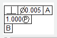
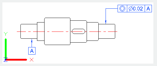
The geometric tolerance is the allowable deviation of shape, profile, direction, position and beat. The feature control box could be created by the TOLERANCE or LEADER or QLEADER command with leader.
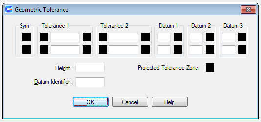
The TOLERANCE dialog box is used to specify the symbols and values for a feature control frame.
Function Description:
After selecting geometry features symbols, the Geometric Dialog box closes and prompts to specify the location to place the feature control frame.
Relative Glossary:
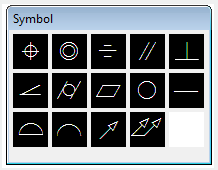
Symbol:
Select a geometric characteristic symbol from "Symbol" dialog box.
Tolerance 1:
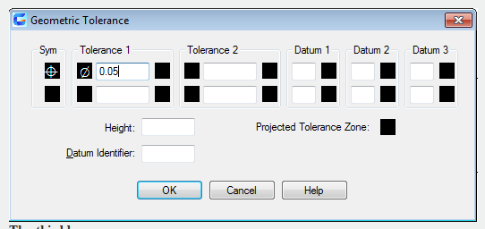
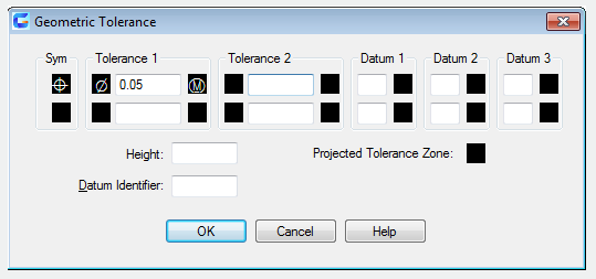
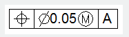
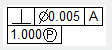
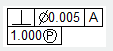
Create the first tolerance value in the feature control frame. The tolerance value means the amount by which the geometric features can deviate from a perfect shape. Users can insert a diameter symbol.
The first box:
Click the first box to insert a symbol. For example, insert a diameter symbol.
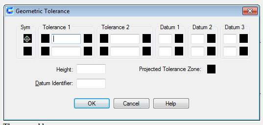
The second box:
Create a tolerance value. Input a tolerance value to the second box.
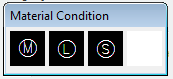
The third box:
Display the "Material Condition" box, from which users could select a modifying? symbol. Those symbols act as modifiers to the geometric characteristic and the tolerance value of features that can vary in size.
Tolerance 2:
Create the second tolerance value in the feature control box. Specify the second tolerance value in the same way as the first one.
Datum 1:
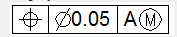
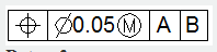
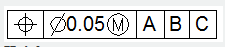
Create the primary datum reference value. The datum reference is composed by a value and a modifying symobl. In theory, the datum is an accurate geometric reference, which is a tolerance zone used to create features.
The first frame:
Create a datum reference value
The second frame:
Display the "Material Condition" box, from which users could select a modifying?symbol. These symbols act as modifiers to the datum reference.
Datum 2:
Create the secondary datum reference in the feature control box, which is in the same way as the primary datum
Datum 3:
Create the tertiary datum reference in the feature control box, which is in the same way as the primary datum reference.
Height:
Create a projected tolerance zone value in the feature control frame. A projected tolerance zone controls the height variation of the extended portion in the fixed perpendicular part, as well the location tolerance controls the tolerance accuracy.
Projected Tolerance Zone:
Insert a projected tolerance zone symbol after the projected tolerance zone value.
Datum Identifier:
Create a datum-identifying symbol consisting of a reference letter. A datum is a theoretically exact geometric reference from which you can establish the location and tolerance zones of other features. A point, line, plane, cylinder, or other geometry can serve as a datum.