GstarCAD 2021 Complete Features Guide
GstarCAD 2021 Complete Features Guide
Contents
- #Perfect Compatibility
- #Flexible Licensing
- #Excellent Performance
- #Innovative Features
- #What's New in GstarCAD 2021

GstarCAD 2021 Completely Guide
The most valuable alternative CAD
GstarCAD 2021 optimizes 3D functionalities with adding a series of new commands. Other new features like Rapid Dist, Import/Export custom settings, and point cloud greatly improve user’s efficiency to obtain dimensional data, transfer user settings, and view point cloud data. Plus, the significant improvements of tool palette and Mtext editor will lighten workload tasks and design process.
Perfect Compatibility
GstarCAD constantly improves its compatibility in all aspects and accomplishes the high compatibility with ACAD. The seamless data format, familiar interface, command structure and user operating habit, ease of use customization settings and applications/add-ons are all ready for you in GstarCAD 2021.
- Data Format
GstarCAD 2021 supports the native DWG/DXF file formats which are completely compatible with ACAD from version 2.5 to 2021. Any CAD drawings based on the DWG/DXF format can be easily handled by GstarCAD. Meanwhile, the drawing files created by GstarCAD also can be handled with other CAD software. GstarCAD 2021 fully realizes bidirectional compatibility with ACAD in data formats.
Furthermore, GstarCAD 2021 even supports various kinds of data file formats and secondary development interfaces. You could create or edit drawings with exactly original ways.

Paired PDF illustration layout — page 3

The mainly file formats and development interfaces between GstarCAD and ACAD.
| Items | GstarCAD | ACAD |
|---|---|---|
| 2.5-2018 DWG/DXF Versions | √ | √ |
| Drawing Templete File (DWT) | √ | √ |
| Drawing standard File (DWS) | √ | √ |
| Customize User interface file (CUI/CUIX) | √ | √ |
| Old Menu File (MNU) | √ | √ |
| Drawing Sheetset File (DST) | √ | √ |
| Hatch Pattern File (PAT) | √ | √ |
| Font File (SHX) | √ | √ |
| Line Type File (LIN) | √ | √ |
| Print Style File (CTB/STB) | √ | √ |
| Import and Export WMF | √ | √ |
| Import and Export SAT | √ | √ |
| Import 3DS | √ | √ |
| Import DGN | √ | √ |
| Export DWF/DWFX | √ | √ |
| Export STL | √ | √ |
| Export EMF | √ | √ |
| DWF Underlay | √ | √ |
| PDF Underlay | √ | √ |
| DGN Underlay | √ | √ |
| Script File (SCR) | √ | √ |
| LISP Development Interface | √ | √ |
| LSP File Loading | √ | √ |
| FAS File Loading | √ | √ |
| VLX File Loading | √ | √ |
| VBA Development Interface | √ | √ |
| Class ARX Development Interface | √ | √ |
| .net Development Interface | √ | √ |
- Concise User Interface
GstarCAD 2021 offers you a concise and familiar interface. The combination of attractive dark color theme and icon designs will reduce your eyes strain. It’s also available for you to display and rearrange elements like the toolbars, display the command bar, switch between workspaces, change the interface themes, customize your own interface and enable the status bar. The toolbars and command bar can also be floated anywhere on the screen or docked as well.

- Familiar Command
You can get start with GstarCAD immediately with the familiar command structure and shortcut system that you have known without any extra training. Whether you're a novice user or an experienced CAD professional, you'll soon be creating drawings using the productivity-enhancing features of GstarCAD.
| GstarCAD Commands | ACAD CommandsGstarCAD Commands | ACAD Commands | |
|---|---|---|---|
| Multiple | Multiple | Superhatch | Superhatch |
| Osnap | Osnap | Redraw | Redraw |
| Qselect | Qselect | Regen | Regen |
| Qleader | Qleader | Scalelistedit | Scalelistedit |
| Spell | Spell | Bedit | Bedit |
| Layerp | Layerp | Render | Render |
| Layoff | Layoff | Flatshot | Flatshot |
| …… |
- Customized Settings
GstarCAD offers several methods to import your customized settings such as CUI, Lisp program, Shortcut settings, Blocks, DWT, Tool palettes, Plotters and so on from other CAD software. Just few minutes, you will find your familiar interface in GstarCAD.
- API and Add-ons
GstarCAD offers friendly development interface such as GRX, .NET, VBA, Lisp etc. Nowadays, hundreds of professional applications and industrial solutions are running on GstarCAD.
For more information about applications/add-ons of GstarCAD, please refer to the link:
https://www.gstarcad.net/application/
Flexible Licensing
Licensing Policy
GstarCAD licensing policy is flexible and simple. We provide both perpetual license and subscription. You are free to choose the license mode and you decide when to upgrade.
Perpetual License
When you choose to buy GstarCAD Perpetual License, you have the right to use it perpetually. You buy it once and it’s forever yours. You are not forced to buy the subscription nor upgrades.
Perpetual License and Subscription Plans
You can buy GstarCAD Perpetual License together with Subscription Plans. Gstarsoft releases a new GstarCAD major version every year, with Subscription Plans you can upgrade to the latest version of GstarCAD.
Yearly Subscription
GstarCAD Yearly Subscription is similar as ACAD Subscription; you can just pay a smaller amount for using GstarCAD 1-year-license.
GstarCAD Upgrades
Gstarsoft releases a new GstarCAD major version every year; you can upgrade your GstarCAD Perpetual License to any newer version, still the Perpetual License!
Licensing Options
GstarCAD not only provides the flexible licensing policy, but also provides the flexible licensing Options. GstarCAD offers Stand-alone and Network licenses, both are available with Soft key (Serial number) and Dongle (USB-key).
Stand-alone license
The software is constrained to a certain host. A license is needed for each computer on which the software will be installed.
Network license
A pool of licenses is available on the server, for use in any computer on the network. You only need to have licenses for the maximum number of simultaneous users expected, not for each computer where the software will be installed.

Excellent Performance
Higher performance plays an important role in GstarCAD. GstarCAD not only provides users with more useful functions constantly, but also delivers great performance in both 2D and 3D operations.
The performance of common-use operations like "OPEN", "QSAVE", "PLOT", "CLIP", "TRIM", "PASTE", "MOVE", "DYNAMIC SELECTION", and more commands are significantly faster than other CAD software. Big drawings could be opened more quickly and save your work in only a fraction of a second.
The chart below provides an overview of the performance of GstaCAD 2021. We build an operation speed comparison of the basic features between GstarCAD and another CAD. The drawing which uses to test the operation time is around 47 MB. To make sure the data validation, same operations will be tested twice and get the average value.
Operation speed from two software's(Unite: Second)
Testing environment:WIN7 64bit; 8G storage; 64bit installation package; Drawing size: 47MB
Chart 1 — GstarCAD 2021 / Other CAD 2021

| Operation | GstarCAD 2021 | Other CAD 2021 |
|---|---|---|
| Open | 2.98 | 3.3 |
| Save | 2.25 | 3.61 |
| Select all | 0.5 | 0.99 |
| Move | 1.64 | 2.35 |
| Copy | 2.44 | 3.34 |
| CTRL+C | 4.58 | 7.05 |
| CTRL+V | 3.35 | 4.85 |
| Mirror | 3.1 | 3.4 |
| Regen | 0.53 | 0.750000000000002 |
| Zoom all | 0.57 | 0.730000000000001 |
| Delete | 0.720000000000001 | 2.43 |
It’s obviously that GstarCAD 2021 is faster than the other CAD software when executing MOVE, SAVE, COPY, ZOOM, and Delete commands. And it is extremely good when executing COPY TO CLIPBOARD command. Besides the chart, GstarCAD also works excellently in ARRAY and EXPLODE command, while another CAD even couldn’t array objects in the same drawing. Additionally, execute EXPLODE by the other CAD software won't get response for a long time. Compare with other CAD software, GstarCAD is far ahead in performance especially for large drawings.
Innovative Features
GstarCAD offers over 100 unique and innovation tools like “Collaboration”, “Area Table”, “Auto Layer”, “Viewport to Layout”, “Autoxlstable”. They are adopted to significantly speed up your drafting speed.
| GstarCAD Innovative Features | Description |
|---|---|
| Autolayer | Automatically switch the current layer while drawing the graph and draws the graphic to the set layer. |
| Area Table | Automatically dimension and count the area of an enclosed object and export the result to a table in the current drawing area. |
| Break Object | Bleaks Objects by intersecting lines and allows to set the gap. |
| Block Break | Breaks or shelter the graphic under the block. |
| Graphic Compare | Compares graphic of two groups of objects or two files. |
| Line2pl | Converts one or multiple connected straight line(s), arc(s) to one polyline. |
| Sptpl | Spline created can be converted to a polyline according to the accuracy (number of segments of the arc). |
| GstarCAD Tools | A set of GstarCAD practical tools to enhance design efficiency, Including Drawing Scale, Rotate Cursor, Draw Axonometric Line, Extension, Normal Connect, etc. |
| Drawing Lock | Turns the drawing into a whole block to prevent be modified by others. |
| Attribute Increment | Specifies attribute of blocks with incremental value, and to modify attribute value of blocks according to the sort method. |
| Define Layout Viewport from ModelSpace(M2LVPORT) | Defines the range of drawing displayed in viewport from the model space, calculate the viewport size based on the set scale and position the viewport in the layout space. |
| Align Tool | Aligns selected objects such as: rectangle, circle, line, spline, arc, pline, block and even 3D model object along X or Y axis coordinates. |
| Arrange Tool | Adjusts the arrangement of multiple objects. It can align multiple objects at left, right, top, bottom and center and also can arrange vertical or laterally. |
| MEASUREGEOM | Supports to measure distance, radius, angle, area, volume sum area and so on. |
| Symmetric Draw | Generates the symmetrical object automatically when drawing an object. |
| Outline Objects | Extracts the outline shape of selected closed objects in a window selection method. |
| Invert Fillet | The FILLET command now offers a new option called Invert. You can create a reverse fillet by this option. |
| Magnifier | Views a specific area of your drawing as a magnifier with the capability of snap points without performing zoom in/out. |
| Barcode & QR Code | Creates Barcode& QR Code by entering data or picking data from drawing. |
| Shortcut Customization(CUSTACC) | CUSTACC command allows you to customize, delete or modify existing command shortcuts. |
| Table Tools | A set of practical tools to draw and edit tables and can export CAD Table to Excel file. |
| AutoXLSTable | Opens Excel file to edit the data and insert it to GstarCAD. It also allows updating the table data after the drawing was modified. |
| Pline Boolean | Supports different Boolean operation options such as union, intersection and subtraction. |
| Batch Print | Batch print drawings with the same drawing frame attribute in a drawing. |
| Arrange Frame | Inserts frames of drawings, calculate according to the size of the frame and then arrange them to a big drawing. |
| GstarCAD Collaboration | Helps to improve project design efficiency and significantly reduce error and cost. |
| … | … |
What's New in GstarCAD 2021
Import, Export and Migrate User Custom Settings New
GstarCAD 2021 supports importing and exporting the settings of current version, as well as importing settings of old version, which enable users to avoid repeating same settings when they install the software. Users can also import Tool Palettes from AutoCAD.

Import and Export Settings of Current Version
You can import and export of settings of current version in the WINDOWS Start menu without starting GstarCAD, which makes the operation more convenient and simpler. And, importing the saved exported settings when the software is reinstalled or Installed on other machines will save plenty of time.

Export Settings of current version: Open windows start menu, find your Gstarsoft item and click “Export the settings of current version”, choose the location you prefer to save the “.cfgbak” file and save it.

Import Settings of current version: Open windows start menu, find your Gstarsoft item and click “Import the settings of current version”, find the “.cfgbak” file and open it.

Exported Settings includes:
-
Options: File locations, Display options, User preferences, Drafting settings, Selection settings and other custom settings
-
Customize User Interface: Workspace, toolbars, ribbon customization, command, keyboard and mouse button customizations
-
Alias file (gacd.pgp)
-
Printer support file
-
Hatch pattern (*.pat)
-
Tool Palettes
-
Template file (*.dwt)
-
Fonts and shapes (*.shx)
-
Line type (*.lin)
-
Font mapping file (gacd.fmp)
Migrate from a Previous Release
GstarCAD 2021 adds a "Migrate from a previous release" feature in the WINDOWS

Start menu program items, which allows users to migrate selected settings of old versions directly to the new version after installation without copying and setup manually under same language. The earliest version that can be migrated is GstarCAD 2016.
Migrated Settings includes:
-
Options: File locations, Display options, User preferences, Drafting settings, Selection settings and other custom settings
-
Customize User Interface: Workspace, toolbars, ribbon customization, command, keyboard and mouse button customizations
-
Alias file (gacd.pgp)
-
Printer support file
-
Hatch pattern (*.pat)
-
Tool Palettes
-
Template file (*.dwt)
-
Fonts and shapes (*.shx)
-
Line type (*.lin)
-
Font mapping file (gacd.fmp)
- After migration from older version, the relevant settings of current version will be overwritten, and can’t be restored.
- After migration from older version, the new functionalities that only current version supports, will be reset to default.
Import AutoCAD Tool Palettes
You can import AutoCAD customized Tool palettes in the WINDOWS Start menu easily. If you installed AutoCAD in your PC, you can just import the file from the path in AutoCAD options. If you need to import AutoCAD customized Tool Palettes from another equipment, the path can be anywhere, but the folder must include AcTpCatalog.atc file.

Before importing an AutoCAD tool palettes, read carefully the following notes:
-
The default blocks of AutoCAD cannot be directly imported into GstarCAD. If you want to import default blocks of AutoCAD to GstarCAD, you need to drag them to the drawing from the Tool Palettes, and add them back to Tool Palettes in AutoCAD, then save the drawing and import.
-
The imported file is only block and command, hatch pattern, light source, constraint, table and other objects haven’t been supported yet.
-
If there is a lack of grip point in the imported dynamic block, probably it’s the result of the imperfect action of the dynamic block.
-
All eligible GstarCAD paths will be detected first when you import the file into GstarCAD directly, the entire Tool Palettes in GstarCAD will be overwritten.
-
The order of the tools list in Tool Palettes after import may be different from that of AutoCAD. The reason is that AutoCAD supports a file recording the order of the tools in Tool Palettes, but GstarCAD does not.
-
If the source DWG drawing location is changed before you import custom AutoCAD Tool Palettes and its tools, the block(s) imported into the palettes in GstarCAD will be unable to be used without that corresponding DWG drawing original saved path.
3D Commands New
A series of new 3D features, such as POLYSOLID, CONVTOMESH, CONVTOSOLID, CONVTOSURFACE, CONVTONURBS, PLANESURF, SURFOFFSET, which enhance the 3D functionality of the software.


PLOYSOLID
You can input the POLYSOLID command or click Ribbon – 3D – Modeling – Polysolid to create 3D solid in a shape of a wall directly or by selecting existing polylines. A polysolid is drawn the same way you draw a polyline, which is created with continuous straight and curved segments.


Paired PDF illustration layout — page 14

After inputting the PLOYSOLID command, you will get 4 options (Object, Width, Height, Justification) in the command line and dynamic input box.
-
Type “Width” or “Height” to set width and height.
-
Type “Justify” to set justification (Left, Center, Right).
-
When you start drawing solid wall after clicking on your first point, it gives you 2 options (Arc, Undo) in the command line and dynamic input box. If you don’t input any of them, you can just continue drawing your lines.
-
If you type “Arc”, it can give you 3 options (Close, Direction, Line), you can draw the arc by 2 points or enter “Direction” to draw the arc by tangency direction.

-
You can also type “Close” to close your polysolids or type “Line” to change back to line again. If you type “Undo”, it will back to previous point.
-
If you type “Object” in dynamic input box or in command line, you can convert existing lines, 2D polylines, arcs, and circles into 3D solids with default height, width, and justification. This feature only allows select objects one by one.

PSOLWIDTH: System variable, sets the default width for the 3D polysolid.
PSOLHEIGHT: System variable, sets the default height for the 3D polysolid.
PLANESURF
You can input PLANESURF command or click Ribbon – Surface – Plan to create a planar surface by selecting closed objects or specifying the opposite corners of a rectangular surface. When the corners of the surface are specified by the command, you can create a surface parallel to the work plane.

SURFU / SURFV: System variable, sets the number of lines displayed on the surface
DELOBJ : System Variable, decides whether to delete defining objects.
SURFOFFSET
1.1.3. 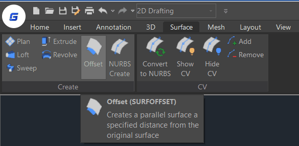
Paired PDF illustration layout — page 15

SURFOFFSET
You can input SURFOFFSET command or click Ribbon – Surface -SURFOFFSET, to create a parallel surface at a specified distance from the original surface.
After selecting the surface and pressing enter, you will get 4 options (Flip direction, Both sides, Solid, Expression) in the command line and dynamic input box.
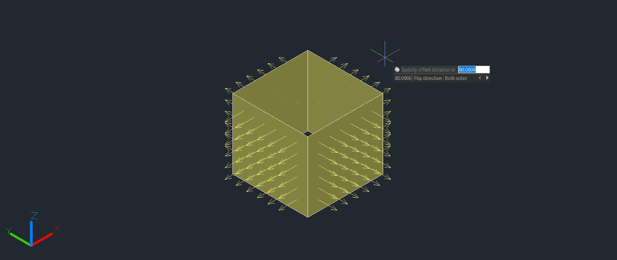
You can Offset the surface in one direction (the arrows will show on one side of the surface) by entering a distance or select the point on the drawing.
- If you type “Flip direction”, the arrows will flip to another side.

- If you type “Both sides”, you can Offset the surface in both directions (the arrows will show on both sides of the surfaces)

- If you type “Solid”, you can Generate the surface to a solid after the offset

- If you type “Expression”, you can enter a formula or equation to specify the distance of the surface offset.

SURFACEASSOCIATICITY: System Variable, when the value is 1, Expression option will be displayed. This option does not update the offset distance default value the next time you enter the command.
SURFACEMODELINGMODE: System Variable, when the value is 1, the surface will be a NURBS surface.
CONVTOMESH
You can input CONVTOMESH command or click Ribbon- Mesh – Convert to MESH to convert eligible 3D objects into meshes, the objects will be smoothed at the same time in the conversion as well.

Eligible objects include: solids, closed polylines, regions, 3D face, 3D surfaces, polygon meshes.
When the 3D entities that are extruded, swept, lofted, and revolved with arcs are converted to meshes, and the number of faces and vertices after conversion cannot be displayed correctly
FACETERMESHTYPE: System Variable, controls the level of smoothness upon conversion (If the mesh type is not set to be optimized, the converted object is not smoothed).
DELOBJ : System Variable, decides whether to delete defining objects.
CONVTOSOLID
1.1.5. 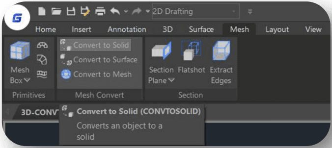
CONVTOSOLID
You can input the CONVTOSOLID command or click Ribbon- Mesh – Convert to SOLID to convert eligible objects to 3D solids.
Eligible objects include:
-
3D meshes that completely enclose a volume
-
Surfaces that completely enclose a volume
-
Closed polylines and circles with a non-zero thickness property; wide polylines must have a uniform width
The Command has following limitations:
-
You can select one or more objects to convert to solid, if any object in your selection set is in invalid for the command, you will be prompted again to select the objects.
-
It’s not available to convert planar surfaces or regions with contiguous edges to 3D solid.
-
It’s not available to convert separate objects to 3D solid. If the surfaces enclose a watertight area, you can convert to a solid with the SURFSCULPT command.
SMOOTHMESHCONVERT: System Variable, only supports value 3. Smoothness and optimization effect won’t be supported in the version.
DELOBJ : System Variable, decides whether to delete defining objects.
CONVTOSURFACE
1.1.6. 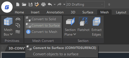
Paired PDF illustration layout — page 18

CONVTOSURFACE
You can input the CONVTOSURFACE command or click Ribbon- Mesh – Convert to SURFACE to convert eligible objects into 3D surfaces.
Eligible objects include: 2D solids, 3D solids, Mesh objects, Planar 3D faces, Regions, Zero-width polylines with thickness, Polylines with global-width, Lines with thickness, Arcs with thickness, Closed plane curve.
SMOOTHMESHCONVERT: System Variable, only supports value 3. Smoothness and optimization effect won’t be supported in the version.
DEOBJ : System Variable, when sets the value to 0/3/-3, the defining objects won’t be deleted, when the value is -1/-2, there will be a two options for users to choose delete or not, when it is 1/2, the defining objects will be deleted.
CONVTONURBS
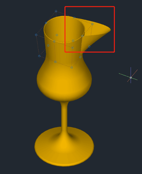
You can input CONVTONURBS command or click Ribbon- Surface – Convert to NURBS to convert solids and procedural surfaces to NURBS surfaces. You can also convert meshes to NURBS surfaces after converting them to a solid or surface by CONVTOSOLID or CONVTOSURFACE command.

There are a series of new functionalities for NURBS control vertices editing and display, such as
- SHOW CV: Shows control vertices. You can adjust the NURBS surfaces by clicking the control vertices, you will get 4 options (Base, Copy, Undo, Exit) in your command line and dynamic input box.

Paired PDF illustration layout — page 20

Base: Moves your control vertices according to the base point and second point you choose.
-
Copy: Copies a new NURBS surface and move it, the original surface won’t be deleted.
-
Undo: Cancels the previous step.
-
Exit: Stops adjusting control vertices.
-
HIDE CV: Hides control vertices.
-
ADD: Adds control vertices. After selecting the object, you will get 2 options (Knots, Direction) to add control vertices and set the position.
-
Knots: Turns off the display of control vertices and allows you to place a point directly on a surface. This option only displays if you select a surface; it does not display for splines.
-
Direction: Specifies whether to add control vertices in the U or V direction. This option only displays if you select a surface; it does not display for splines.
-
REMOVE: Removes control vertices. There are at least 2 control vertices in each direction.
DELOBJ : System Variable, decide whether to delete defining objects.
Point Cloud New

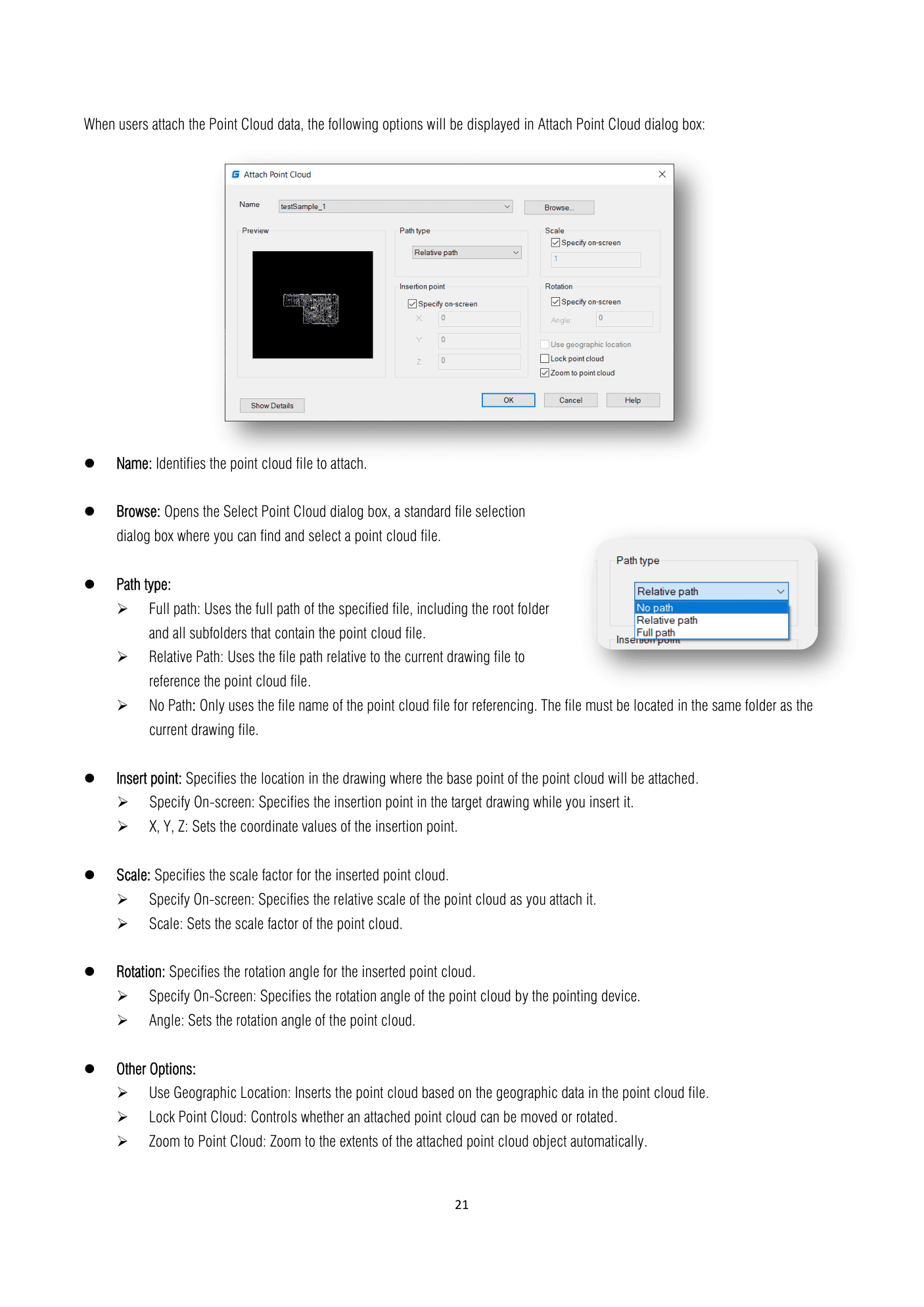
GstarCAD 2021 supports point cloud file extensions (.rcp and .rcs) as attachment in a drawing. The point cloud is inserted at the specified coordinates, based on the location of the Insertion object snap. Users can apply object color and RGB scan colors to display point cloud data.
When users attach the Point Cloud data, the following options will be displayed in Attach Point Cloud dialog box:

-
Name: Identifies the point cloud file to attach.
-

Browse: Opens the Select Point Cloud dialog box, a standard file selection dialog box where you can find and select a point cloud file.
-
Path type:
-
Full path: Uses the full path of the specified file, including the root folder and all subfolders that contain the point cloud file.
-
Relative Path: Uses the file path relative to the current drawing file to reference the point cloud file.
-
No Path: Only uses the file name of the point cloud file for referencing. The file must be located in the same folder as the current drawing file.
-
Insert point: Specifies the location in the drawing where the base point of the point cloud will be attached.
-
Specify On-screen: Specifies the insertion point in the target drawing while you insert it.
-
X, Y, Z: Sets the coordinate values of the insertion point.
-
Scale: Specifies the scale factor for the inserted point cloud.
-
Specify On-screen: Specifies the relative scale of the point cloud as you attach it.
-
Scale: Sets the scale factor of the point cloud.
-
Rotation: Specifies the rotation angle for the inserted point cloud.
-
Specify On-Screen: Specifies the rotation angle of the point cloud by the pointing device.
-
Angle: Sets the rotation angle of the point cloud.
-
Other Options:
-
Use Geographic Location: Inserts the point cloud based on the geographic data in the point cloud file.
-
Lock Point Cloud: Controls whether an attached point cloud can be moved or rotated.
-
Zoom to Point Cloud: Zoom to the extents of the attached point cloud object automatically.
-
Show / Hide Details: Includes number of points, Point Cloud unit, and Point Cloud data.

Display with RGB Scan Color or Object Color
GstarCAD 2021 allows you to display the point cloud data with RGB scan color or Object color by inputting POINTCLOUDSTYLIZE command. And execute REGEN to refresh the display effect of the inserted point cloud.

Paired PDF illustration layout — page 22


Paired PDF illustration layout — page 22
Rapid Dist New
GstarCAD 2021 supports new RAPIDDIST command, which measures distance and angle between 2D objects along X, Y axis rapidly by moving your mouse .
Distances that only can be measured along X, Y axis based on the position of your mouse, are displayed dynamically as you move your mouse over and between objects. Angles between the objects touched by distance lines, are displayed dynamically at the same time.

The command only can be used under WCS, and only measure the 2D objects. And the angles of the blocks can’t be measured.

Type “Settings”, you can set unit conversion and scale in
setting window.
Type “Record”, You can save the current result in command line window,
which is convenient to check or copy data to other documents.

Paired PDF illustration layout — page 23

Tool Palettes Improvement
In GstarCAD 2021, Users can hatch objects with hatch patterns from Tool Palettes by clicking and move the mouse on the object. Users can easily modify the properties of the hatch patterns as well.

Paired PDF illustration layout — page 24

The Tool Properties dialog box, accessed on the shortcut menu of hatch pattern tool.
Options in Properties dialog box:
-
Name: Identify the name of the hatch pattern in Tool Palettes
-
Description:Self-edited notes.
-
Tool type: Hatch.
-
Type: Opens hatch pattern type dialog box to select one type.
-
User-defined: Changes the definitions of the lines which make up the hatch.
-
Custom: Displays Self-created custom hatch pattern.

Paired PDF illustration layout — page 24
- Predefined: Displays a selection of ANSI, ISO, and other industry-standard hatch patterns

-
Pattern name: Displays a selection of ANSI, ISO, and other industry-standard hatch patterns. The Pattern option is not available when Type is set to User-defined.
-
Auxiliary scale: Multiplies the current scale setting by the plot or dimension scale. The Pattern option is not available when Type is set to User-defined.
-
Dimscale: Dimension scale, control the overall scale of dimensions.
-
Plot scale: Specifies a precise scale of the hatch to the paper when you plot the drawing.
-
None: Doesn’t support auxiliary scale.
-
Angle: Specifies an angle for the hatch pattern relative to the X axis of the current UCS.
-
Scale: Expands or contracts a predefined / custom pattern.
-
Space: Specifies the spacing of lines in a user-defined pattern.
-
ISO pen width: Scales an ISO predefined pattern based on the selected pen width. This option is available only when Type is set to Predefined and Pattern is set to one of the available ISO patterns.
-
Double: For user-defined patterns, draws a second set of lines at 90 degrees to the original lines, creating a crosshatch.
-
Layer, Color, Linetype, Plot style, Lineweight, Transparency: Override the current drawing property settings.
Mtext Editor Improvement
New enhancement of MText editor supports Numbering, Superscript, Subscript, Combining Paragraphs, Matching Text format and Adding Deletelines to selected text.


Paired PDF illustration layout — page 26

Upgrade and downgrade of serial Numbers:
-
Press Tab to increase the selected list item by one level.
-
Press Shift+Tab key to lower the selected list item by one level.
-
Press Enter to continue Numbering.
-
Press Shift+Enter to end Numbering.
Options in Numbering list:

-
Off: Remove letters, numbers and bullets from the selected text to which the list format is applied. Does not change the indentation state.
-
Lettered: Apply a list format that uses letters with periods for items in the list. If the list contains more items than letters, you can continue the sequence with two letters.
-
Numbered: Apply a list format that uses numbers with periods for items in the list.
-
Bulleted: Apply a list format that uses bullets for items in the list.
-
Start: Start a new sequence of letters or numbers in the list format. If the selected item is in the middle of the list, the unselected items below the selected item will also become part of the new list.
-
Continue: Add the selected paragraph to the last list above and continue the sequence. If a list item is selected instead of a paragraph, the unselected items below the selected item will continue the sequence.
-
Allow Auto Bullets and Numbering: Apply list formatting as you type. The following characters can be used as punctuation after letters and numbers but cannot be used as bullets: period “.”comma “,”, right bracket “)”, right angle bracket “>”, right square bracket “]”, and right curly brackets “}”.
-
Allow Bullets and Lists: If you select this option, the list format will be applied to all plain text in multi-line text objects that look like lists.
Gstarsoft Co., Ltd
Gstarsoft is a recognized leading provider of 2D/3D CAD software and solutions for industries involving AEC, Mechanical and Manufacturing, Electrical and Electronics, GIS, Survey and Mapping, Civil Engineering, etc. With 27-year proud history of technology innovation and practice, Gstarsoft provides fast, powerful and DWG-compatible CAD software and solutions for worldwide customers and partners. Today there are 600,000+ installations of GstarCAD products and 30,000,000+ users of DWG FastView in more than 100 countries around the world.


PDF page 8 — additional source text
0
1
2
3
4
5
6
7
8
Operation Speed Comparison  (Unite:Second)
PDF page 8 — additional source text
GstarCAD 2021
Other CAD 2021