CHAMFER command
The CHAMFER command is used to create chamfers for selected object.
Command Access:
Ribbon : Home > Modify > Fillet > Chamfer
Menu : Modify > Chamfer
Command : CHAMFER
Command Prompts:
Select first line or [Undo/Polyline/Distance/Angle/Trim/mEthod/Multiple]:
Select second line or shift-select to apply corner:
Function Description:
When creating a chamfer, the specified distance and angle are applied on it by selection order.
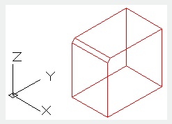
Users could chamfer straight lines, polylines, Rays and Xlines. They could also chamfer 3D solids and surfaces. To create a chamfer for mesh objects, they should be firstly converted to solid or surface.
Relative Glossary:
First line:
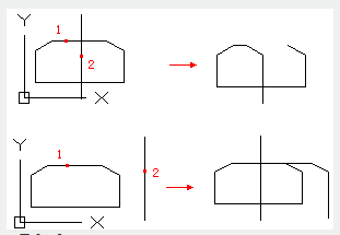
Specify the first of two lines required to define a 2D chamfer, or the edge of 3D solid to chamfer. If selected straight lines or polylines, they will adjust their length to form chamfer edge. When selecting objects by pressing SHIFT key, users could use 0 to instead current chamfer distance. If selected 2D polylines, they must be adjacency or separated by at most one line. If they are separated by another polyline, the CHAMFER command will create a chamfer and delete the separation line.
Enter surface selection option:
Enter O or press ENTER to specify the selected surface to be base. Enter N to select an adjacent surface. After selecting base and chamfer distance, users should select edges on the base to be chamfered. They could also select all edges at one time.
Edge:
Select one edge for chamfering.
Loop:
Convert to "Edge" mode.
Edge: Select all edges on the base.
Undo:
Restore the last operation performed in command.
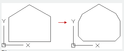
Polyline:
Chamfer the whole 2D polyline.
When polylines are intersecting, selecting “Polyline” option could chamfer each polylines at each vertex. Chamfering segment and previous Multiple lines compose a new polyline. If the component line of polyline is too short to chamfer, it will be not chamfered.
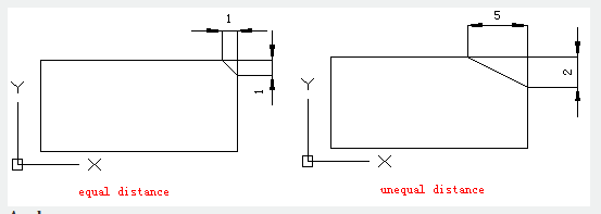
Distance:
Specify the distance from chamfer to specified endpoint. If the two distances are all specified to 0, it will extend or trim the selected two lines and join the two lines at one point.
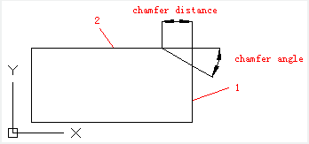
Angle:
Specify chamfer distance by chamfer distance of the first line and angle of the second line.
Trim:
This option is used to control whether to trim specified line to the end point of chamfer.
Note: the “Trim” option could specify TRIMMODE system variable to 1; the “No trim” option could specify TRIMMODE system variable to 0. If the TRIMMODE system variable is specified to 1, the CHAMFER command will trim intersection line to the end point of chamfer. If the second selected line is not intersected with the first one, it will be extended. If the TRIMMODE system variable is specified to 0, it will create chamfer rather than trim selected line.
Method:
This option is used to control methods of creating chamfer, by two distances or one distance and one angle.
Multiple:
Create chamfers for more than one set of objects.
Expression:
Control chamfers distance by mathematics expressions.