ATTDEF command, attribute definition
The ATTDEF command is used to create and save data attribute definition in block.
ATTDEF (display Definition dialog box), -ATTDEF (display command line prompts)
Ribbon: Home > Block > Define Attribute
Ribbon: Insert > Block Definition > Define Attribute
Menu: Draw > Block > Define Attributes...
Function Description:
The attribute of block could be contained in block definition. Users could save data in attribute, such as number of parts, product name, etc.
Inputting “-attdef” under the command prompt, it will display options.
Relative Glossary:
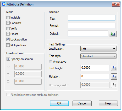
Mode : When inserting a block, it is used to set associative attribute value for it. The default value is saved in AFLAGS system variable. Users could change the default mode of new attribute value by changing AFLAGS value, but the current attribute definition will remain unchanged..
- Invisible : Checking the Invisible option, the attribute value will not be displayed or printed when inserting a block. The ATTDISP could replace the Invisible mode.
- Constant : Checking the Constant option, it will assign a constant value for attribute value.
- Verify : Checking the Verify option, it will prompt to verify the attribute value when inserting a block.
- Preset : Checking the Preset option, it will set the attribute value to be default when inserting a block with preset attribute.
- Lock position : Checking the Lock position option, it will lock the attribute location in block reference. After unlocked, the attribute could be moved relative to other parts of block. The block could be edited by grips. The attribute of Mtext could also be adjusted.
- Multiple lines : The specified attribute value could contain Mtext. Checking the Multiple lines option, the width of boundary of attribute could be specified.
Attribute : Specify the attribute value.
- Tag : Make tags for attributes displaying in a drawing. Input the tag with any combining characters except space. Lowercases will automatically change into uppercases.
- Prompt : Display the prompt when inserting a block with attribute definition. Without inputting prompt, the attribute tag will be used as prompt. Checking the Constant option under Mode, the Prompt option will be disabled.
- Default : Specify the default attribute value.
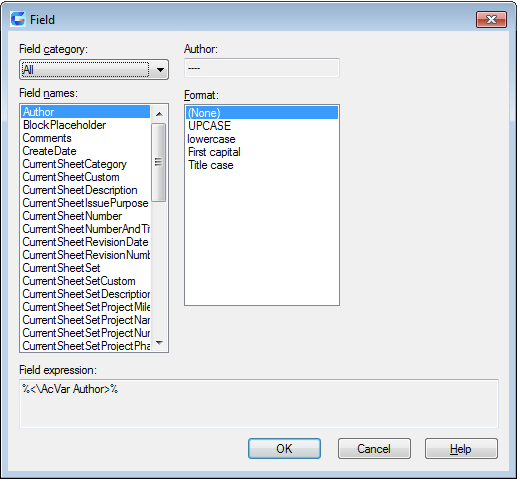
“Insert Field” button : Display the Insert Field dialog box. Users could insert a field as an attribute or one part of attribute.
“Multiline editor” button : After selecting the “Multiple lines” mode, it will prompt to specify location of multiline attribute.
Insertion point : Specify the location of insertion point. Inputting coordinates or selecting “specify on-screen” option to specify the attribute location by pointing device. The attribute is associated with object.
- Specify on-screen : After closing the “Attribute Definition” dialog box and the prompt of “specify start point” displays. Specify the attribute location by pointing device. The attribute is associated with object.
X : Specify the X coordinate of attribute’s insertion point.
Y : Specify the Y coordinate of attribute’s insertion point.
Z : Specify the Z coordinate of attribute’s insertion point.
Text Settings : Set the justification, style, height and rotation of attribute text.
- Justification : Specify the justification of attribute text. Users could get more information about Justification by referring to TEXT command.
- Text style : Specify the preset style of attribute text. Display the currently loaded text style. To load or create a text style, users could refer to STYLE command.
- Annotative : Specify the attribute to be annotative. If the block is annotative, its attribute will be matched with block.
- Text height : Specify the attribute text height. Inputting a value or selecting “Height” to specify it by pointing device. The height is a measured value from original point to specified position. If selected a text style with a fixed height (nonzero) or selected “Align” option in “Justification” list, the Text Height option will be disabled.
- Rotation : Specify the attribute text rotation angle. Inputting a value or selecting “Rotate” to specify it by pointing device. The rotation angle is a measured value from original point to specified position. If selected “Align” or “Fit” option, the Rotation option will be disabled.
- Boundary width : Word wrap to next line. Specify the maximum length of one line in Mtext attribute. The value 0.000 means there is no restriction of text length in one line. This option is not suitable for single text.
Align below previous attribute definition : Align the attribute tag below previous attribute definition. If there is no created attribute definition, this option is disabled.
Relative Glossary:
- Invisible : Checking the Invisible option, the attribute value will not be displayed or printed when inserting a block. The ATTDISP could replace the Invisible mode.
- Constant : Checking the Constant option, it will assign a constant value for attribute value.
- Verify : Checking the Verify option, it will prompt to verify the attribute value when inserting a block.
- Preset : Checking the Preset option, it will set the attribute value to be default when inserting a block with preset attribute.
- Lock position : Checking the Lock position option, it will lock the attribute location in block reference. After unlocked, the attribute could be moved relative to other parts of block. The block could be edited by grips. The attribute of Mtext could also be adjusted.
- Multiple lines : The specified attribute value could contain Mtext. Checking the Multiple lines option, the width of boundary of attribute could be specified.