Add Geometric Tolerances
Overview of Geometric Tolerances
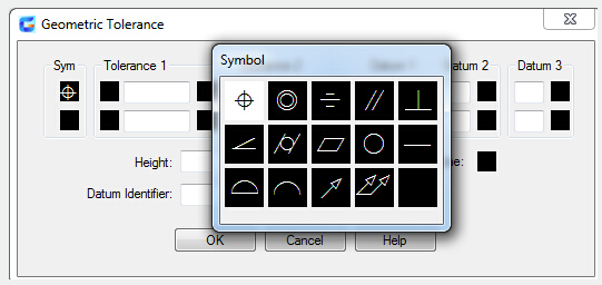
Geometric tolerances indicate acceptable deviations of form, profile, location , orientation and runout of a feature. You can create geometric tolerances with TOLERANCE or LEADER , resulting in them being created with or without leader lines,
A feature control frame can have two or more parts. In the first feature control frame you will find a symbol representing the geometric characteristic like location, profile, form, orientation or runout, to which a tolerance is being applied to. Straightness, flatness, circularity or cylindricity are determined by form tolerances and line and surface are controlled by profiles.
Feature control frames can be modified with most editing commands, you can use the object snap modes to snap to them and you can use grips to edit them.
Material Conditions
Material conditions apply to features that can vary in size.
The value of the tolerance is found in the second component. The tolerance value can be preceded by a diameter symbol and followed by a material condition symbol, which depends on the control type.
Material conditions apply to features that can vary in size:
- A feature will contain the maximum amount of material stated in the limits with maximum material condition (symbol M or MMC).
At MMC, a hole will be attributed with a minimum diameter and a shaft with a maximum diameter. - A feature will contain the minimum amount of material stated in the limits with least material condition (symbol L or LMC).
- At LMC, a hole will be attributed with a maximum diameter and a shaft with a minimum diameter.
- A feature can be any size within the stated limits with Regardless of feature size (symbol S or RFS).
Datum Reference Frames
Maximum three optional datum reference letters and their modifying symbols can be added to the tolerance values in the feature control frame. You make measurements and verify dimensions with a datum, which is a theoretically exact point, axis or plane. Two or three mutually perpendicular planes perform this task best and joined together they are called the datum reference frame.
Projected Tolerance Zones
To make the tolerance more detailed, you can use Projected tolerances.
Besides positional tolerances, Projected tolerances are identified to make the tolerance more explicit. Projected tolerances can for instance control the perpendicularity tolerance zone of an embedded part.
Before the symbol for projected tolerance a height value is added, to determine the minimum projected tolerance zone. As shown in the below picture, the projected tolerance zone height and symbol will appear in a frame below the feature control frame.
Composite Tolerances
If you have two tolerances for the same geometric characteristic of a feature or if features have different datum requirements, you use a composite tolerance. One tolerance relates to a pattern of features and the other one to each feature within the pattern. The individual feature tolerance is more restrictive than the pattern tolerance.
The point at which datums A and B intersect is called the datum axis and it presents the point from which the position of the pattern is calculated.
The diameter of the pattern of holes as well as the diameter of each individual hole should be determined by a composite tolerance.
You have to identify the first line of a feature control frame and select the same geometric characteristic symbol for the second line of the feature control frame, if you want to add composite tolerances to a drawing. To create a second line of tolerance symbols, you have to expand the geometric symbol component over both lines.